the bias is fall to only a few ma
What happens if you warm the heatsink a bit with an hair dryer? Does the bias goes up to previous value?
My buffer is not finished yet.
I am now listening at this output stage (one channel) under 50v rails, but into a NFB loop, driven by a LME49810 chip.
That sounds great.
I need to try outside the loop. ( and also with only one pair into the loop)
After two hours running, the (huge = 40 x 12 x 8cm) heatsink is just leaving the cold.
That changes from my class A amps.
That sounds great.
I need to try outside the loop. ( and also with only one pair into the loop)
After two hours running, the (huge = 40 x 12 x 8cm) heatsink is just leaving the cold.
That changes from my class A amps.
Last edited:
from post # 85 Hello again
thanks a lot for your help, ..sound bad for me,my scope can't reach above 20mhz.is it placing paralel L and R on speaker output will help to prevent oscillation?
last night i replace burned transistor and emmiter resistor,and i'm lowering the bias till 10 to 15ma with load condition,i play the music again with moderate volume for about 1.5 to 2hours,and everything is fine,but the first five minutes the amp turn on,the sound is bad,maybe i set the bias too low,but after five minutes,the sound going normal
20 MHz is enough for the verify of oscillating.
But here an other schematic (darlington, less hfe, ~ 1000) with more stability and less critical against parasitic effects. This means less risk of unwanted oscillation. Please note, your voltage amplifier stage now must provide 10 times more signal current to drive this stage.
There are follow measuring parameter: 10Vss, 100 KHz, 30mA idle current through the output power stage and Load: 8 ohms
therefore not good THD
Attachments
I am now listening at this output stage (one channel) under 50v rails, but into a NFB loop, driven by a LME49810 chip.
That sounds great.
I need to try outside the loop. ( and also with only one pair into the loop)
After two hours running, the (huge = 40 x 12 x 8cm) heatsink is just leaving the cold.
That changes from my class A amps.
wow.. congratulation bobodioulasso
,you are right,this output stage sounds great,but the two things that we must carefull,the bias and oscillation problem,if these problems are solved,i'm sure this would be a great amp.20 MHz is enough for the verify of oscillating.
But here an other schematic (darlington, less hfe, ~ 1000) with more stability and less critical against parasitic effects. This means less risk of unwanted oscillation. Please note, your voltage amplifier stage now must provide 10 times more signal current to drive this stage.
There are follow measuring parameter: 10Vss, 100 KHz, 30mA idle current through the output power stage and Load: 8 ohms
therefore not good THD
thank you very much tiefbassuebertr
,i'm still using the schematic which was you give to me previously,it's great,i'm still seeking the ideal idle current for this circuit,this did not want too high nor too lowif these problems are solved,i'm sure this would be a great amp.
Hi Tomat
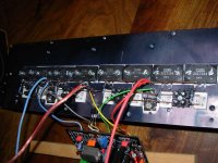
I have no oscillation issue. I put 10 ohms resistors into every output bases.
I have no thermal issue.
Yesterday, i ran 30mA bias per device and this was stable from cold to warm.
Today i lowered to 20 ma: the heatsink stays cold when normal listening.
If it can help i use 2SC5171 as Vbe mult., fitted on the heatsink.
As soon as i can find my camera cable, i will post pics.
Last edited:
Hi Tomat
I have no oscillation issue. I put 10 ohms resistors into every output bases.
I have no thermal issue.
Yesterday, i ran 30mA bias per device and this was stable from cold to warm.
Today i lowered to 20 ma: the heatsink stays cold when normal listening.
If it can help i use 2SC5171 as Vbe mult., fitted on the heatsink.
As soon as i can find my camera cable, i will post pics.
Hi
 that's great,i'm happy to hear your news ,maybe i must change to 2SC5171 too
thanks
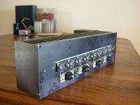
I found it.
excellent job
,looks very simple,not much parts.bobodioulasso,what value resistors for R18 and R19 that you are use (the resistors which are connect in series from base q50 to q51 on original schematic)
thank you
I have only one Vbe mult in the middle of the current sources.
I enter symetrically into the output stage.
It certainly could be used also in a symetrical way. SC5171 /SA1930.
I must say the current sources and the first EF stage are integrated into the chip.
But the principle is indentical.
I do not know why you have such high value resistors in your Vbe.
Input impedance?
Anyway, i am quite shure you can make things better fitting this Vbe on the heatsink. That is compulsary to track temperature.
Then you need to set bias when warm.
If you get distortion when cold, then the Vbe is not correct.
Attachments
Last edited:
I have only one Vbe mult in the middle of the current sources.
I enter symetrically into the output stage.
It certainly could be used also in a symetrical way. SC5171 /SA1930.
if you don't mind,would you please to send me your schematic?,i'm little bit confuse
thanks very much
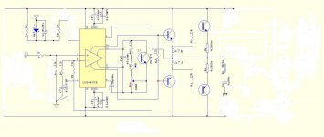
This is a bit far from your schematic, at first sight.
This is a triple Ef as the first EF is inside the chip. current sources also.
I will do nearer from your buffer but i need to order some transistors first.
thank you,now i'm understand
,the 0,1uf capacitor which is see on your first schematic make me confused,but now,it's clearwhat transistors that you are use on driver stage?the stage before output transistors
I do not know why you have such high value resistors in your Vbe.
Input impedance?
Anyway, i am quite shure you can make things better fitting this Vbe on the heatsink. That is compulsary to track temperature.
Then you need to set bias when warm.
If you get distortion when cold, then the Vbe is not correct.[/QUOTE]
i can't going with lower value resistors on there,the minimum value is 13k for both two resistors,if i'm going lower,the output transistors will blow,now i'm using around 14,5k.it resulting bias at output around 10ma at idle.
yes,i was do that also,fitting vbe mult on same heatsink with output q.
bobodioulasso,can you explain me " the Vbe is not correct ",do i have wrong value or mismatch transistors maybe?
thanks very much
the minimum value is 13k
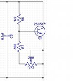
If the resistor (1) from collector to base is deacreased, then you can decrease the resistor (2) fom base to emmitor.
Resistor 2 is better as a 25 turns.
Generally, it is a 25 turns pot serial connected to a resistor. Such as only a fraction of the equivalent resistor can vary. (trimming)
In your case, with a symetrical Vbe, vhen setting the bias, you also act on the offset.
The two potentiometer have to be set alternatively by small quantities checking for bias and offset. Two multimeters are better.
You will never blow anything if you connect your amp to the mains through a light bulb. (serial connected).
It will lit and limit the current if there is a problem.
...10mA bias per device is OK but every output transistor needs bias current. Check for sharing.
PS: the diode strip from the Wahab schematic - fitted on heatsink - will work too in place of Vbe mult.Though, i would keep the current sources. (1N400x are easier to fit on the heatsink)
For driver stage, i use 2SA1294/2SC3263 but they are overkill and a bit slow. Smaller and faster devices should produce better highs.
the Vbe is not correct
Vbe transistors temperature curves have to match (opposite slopes) the drivers and output ones.
A poor temp. regulation can be due to a wrong choice.
BD139/140 are often seen at this place.
Last edited:
If the resistor (1) from collector to base is deacreased, then you can decrease the resistor (2) fom base to emmitor.
Resistor 2 is better as a 25 turns.
Generally, it is a 25 turns pot serial connected to a resistor. Such as only a fraction of the equivalent resistor can vary. (trimming)
In your case, with a symetrical Vbe, vhen setting the bias, you also act on the offset.
The two potentiometer have to be set alternatively by small quantities checking for bias and offset. Two multimeters are better.
You will never blow anything if you connect your amp to the mains through a light bulb. (serial connected).
It will lit and limit the current if there is a problem.
...10mA bias per device is OK but every output transistor needs bias current. Check for sharing.
PS: the diode strip from the Wahab schematic - fitted on heatsink - will work too in place of Vbe mult.Though, i would keep the current sources. (1N400x are easier to fit on the heatsink)
For driver stage, i use 2SA1294/2SC3263 but they are overkill and a bit slow. Smaller and faster devices should produce better highs.
Vbe transistors temperature curves have to match (opposite slopes) the drivers and output ones.
A poor temp. regulation can be due to a wrong choice.
BD139/140 are often seen at this place.
thank you bobo
,i have use the turning pot also for R2,but i think i must adjust the value again,the bias is too low at this moment,they not reach 4ma at output device,and maybe i must replace the bd139/140 also- Status
- This old topic is closed. If you want to reopen this topic, contact a moderator using the "Report Post" button.
- Home
- Amplifiers
- Solid State
- Help with this amp