Hi
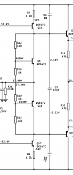
C3 is there to provide a low Z between the bases of the output transistors, at AC. It allows the PNP driver to turn off the NPN output, and vice-versa. A transistor can turn on faster than it can turn off. The residual charge in the base may cause the transistor not to turn off before the other polarity device turns on. The base must be actively discharged because the possible cross-conduction can quickly become catastrophic.


C3 is there to provide a low Z between the bases of the output transistors, at AC. It allows the PNP driver to turn off the NPN output, and vice-versa. A transistor can turn on faster than it can turn off. The residual charge in the base may cause the transistor not to turn off before the other polarity device turns on. The base must be actively discharged because the possible cross-conduction can quickly become catastrophic.
Hi
C3 is there to provide a low Z between the bases of the output transistors, at AC. It allows the PNP driver to turn off the NPN output, and vice-versa. A transistor can turn on faster than it can turn off. The residual charge in the base may cause the transistor not to turn off before the other polarity device turns on. The base must be actively discharged because the possible cross-conduction can quickly become catastrophic.
Hi CBS
thanks for the information
,so is that mean if i give larger value for c3 it will turn off the output transistor more quickly?and i'm sorry for my stupid question
,you say the base must be actively discharge,how does the way?thanks,sorry for my poor english
with the parts, you could build a far better amplifier, and
yet, they will be some components left for another project...
the ouput transistors are legendary good and currently no more
available unless they are fake...
Hi wahab
thanks,i have some transistors left,do you have any suggestion for schematic? that may i can build for next project
Hi wahab
thanks,i have some transistors left,do you have any suggestion for schematic? that may i can build for next project
it depends on your power requirement, but personally, i have a
preference for symetrical differentials..
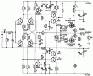
here a schematic from ELEKTOR , the mini crescendo..
it needs some minor tweakings , especialy a more serious
compensation that the one proposed in the original article
wich rely on the mosfet input capacitance...
also, the input transistors are not adequate, use 2SC2240/2SA970
instead of the BC546/556....
Attachments
it depends on your power requirement, but personally, i have a
preference for symetrical differentials..
here a schematic from ELEKTOR , the mini crescendo..
it needs some minor tweakings , especialy a more serious
compensation that the one proposed in the original article
wich rely on the mosfet input capacitance...
also, the input transistors are not adequate, use 2SC2240/2SA970
instead of the BC546/556....
thank you for the schematic
,i think the original 2sk134 are a bit hard to find now,beside quite expensive also,see on ebay near $25See also Nelson Pass F5, doubling the outputs. Extremely simple to build, warranted astounding results.
http://www.firstwatt.com/products.htm
http://www.firstwatt.com/products.htm
Last edited:
Here the original datasheet of your speakers type No 830845:My woofers are: 2 X Peerless xxls 12" 8ohms/75 liters closed boxes
Riviera Acoustics - 12" XXLS Subwoofer
I am now planning to build a monster amp, just for fun. Or may be just power buffers, in order to try different front ends.
..I am curious of every "exotic" design.
830845 XXLS 12″ Subwoofer Peerless Datasheet
the power handling mentioned here are follow:
100h RMS noise test (IEC) 175W
Long-term Max Power (IEC 18.3) 350W
Please note, this is the electrical input power handling, not the mechanical power handling !!! The mechanical power handling (especially below 50Hz in your enclosure) is much more lower
My recommendation for this speaker is an amplifier with 160W into 4 ohms (80 watts for 8 ohms, 28Vss output voltage). If you provide instead of this value only half or twice of this output power (i. e. 80W resp. 320W) means this only a different in SPL of - resp. +3 db, not really a big difference
The power supply should have large version, so that no audible compression effects occurs. This means at least 2x32V/10A-15A main transformer, at least 47mF respectively. 47.000uF 63V for each half, e. g. follow:
http://www.ftcap.de/downloads/elektrolyt/datenblaetter_2009/GW2009.PDF
no audible compression is much more important than 100 or 200 watt more output power. More output power than 160W for this Peerless transducer isn't nessecary.
here the simulated frequency response without any effects through choised location and without any room effects
Attachments
Last edited:
See also Nelson Pass F5, doubling the outputs. Extremely simple to build, warranted astounding results.
First Watt: Products
180w /channel power dissipation for 25W output with 1% dist....
that makes close to 500W for two channels counting
the power supply losses..
the F5 is surely simple to build, but unless you use it
to warm your room, it s not exactly a good design..
the concept has been explored back in the late 70s...
the elektor crescendo is good, and can be easily modified
to use a classical emitter follower pair, the likes that
are used in TOMAT s amp..his 2SA1302/2SC3281 are
very good , unfortunatly, toshiba doesnt produce them anymore...
a darlington would also made it if it s a fast one....
Efficiency is one thing, results an other one.
Have you ever listened to an F5?
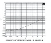
Where are the 1% distortion?
Look at the dist. figure shape. (extremely low at low level increasing regularly)
Important for details restitution.
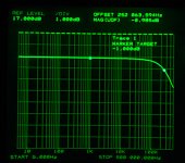
Look also at a the frequency response figure. Very rare in audio.
Opposite to you, i do not claim the creshendo is a bad design.
But you have better to build an F5 and listen, you could be surprised.
(not even the need of a PCB)
Have you ever listened to an F5?
Where are the 1% distortion?
Look at the dist. figure shape. (extremely low at low level increasing regularly)
Important for details restitution.
Look also at a the frequency response figure. Very rare in audio.
Opposite to you, i do not claim the creshendo is a bad design.
But you have better to build an F5 and listen, you could be surprised.
(not even the need of a PCB)
Attachments
Here the original datasheet of your speakers type No 830845:
Thanks, it's very kind from you to have done all this for me.
...I had already done some simulations prior to building my subs.
My speakers are 8 ohms not 4.
I actually use 70 volts rails and 2 x47000 uf (wide Mlytics). 750 VA xformer
I do not totally agree with you. Higher rails result in a better headroom feeling ...
I get today a Dynacord L1600 (same as Electro Voice P2000) for service and maintinance together with a Service manual. By study the schematic I think to your wish in this forumI am now planning to build a monster amp, just for fun. Or may be just power buffers, in order to try different front ends.
..I am curious of every "exotic" design.
For an universal monster amp this topology could be a good baisc for such a project. Here the addresses for order schematics resp. service manuals (as I know, without costs by sending as PDF attachements)
Dynacord "L 1600"
http://www.sonoloc.ch/images/dynacord_l1600.jpg
DYNACORD – Distribution – Europe – France
or Electro Voice (EV) "P 2000"
http://www.electrovoice.com/documents/ev/P_2000_Owners_Manual.pdf
and for order schematic resp. service manual
Electrovoice
Thanks, it's very kind from you to have done all this for me.
...I had already done some simulations prior to building my subs.
My speakers are 8 ohms not 4.
I actually use 70 volts rails and 2 x47000 uf (wide Mlytics). 750 VA xformer
I do not totally agree with you. Higher rails result in a better headroom feeling ...
Do you want to drive each speaker with a separate amp? If yes, you are right, there are 8 ohms (you must have separate chambers for each speaker). In other case you can choice either 4 ohms (parallel connect) or 16 ohms (serial connect). When both transducers see the same chamber, only the last is possible, i. e. one power amp device for drive both Peerless transducers, not two amp devices !!!
"Higher rails" ??? Mean you higher voltages at the rails? Better headroom feeling you observe, if the upper acoustical crossover frequency for your subwoofer low pass network transfer function is higher than approx 80 Hz and at the same time lower than 4-th order (BU-IV or LR-IV) character.
Unfortunately this is fact by the most subwoofer crossover.
Basically, I do not think a lot of small subwoofer enclosures. But to get some satisfactory results, you should be choice the upper crossover frequency arround 60 Hz by at least 24dB/Oct (4th order Butterworth or Linkwitz Riley) Better even 36db/okt.
Please also note that the acoustical high pass function of your main speaker (satellite box) must be exact corresponding (mirror-symmetric), i. e. a carefully high pass network must be create (at best a passive network, that consists one air inductivity (air coil), one foil capacity without electrolytic devices und two resistors); variable active crossover networks unfortunately useless without additional complicated equalization active network. Therefore I don't recommend active network for this. This is because your satellite box provides their own transfer function, depends from the size, whether there are closed or vented box and also depends on the chosen place of installation and the room size.
The royal way of course is a high quality digital processing but that I mentioned previously, the second-best and more user-friendly solution.
Last edited:
Efficiency is one thing, results an other one.
Have you ever listened to an F5?
Where are the 1% distortion?
Look at the dist. figure shape. (extremely low at low level increasing regularly)
Important for details restitution.
Look also at a the frequency response figure. Very rare in audio.
Opposite to you, i do not claim the creshendo is a bad design.
But you have better to build an F5 and listen, you could be surprised.
(not even the need of a PCB)
F5 has its nice sound from how it driving the speaker. The speaker itself has poor linearity and efficiency, more than 20% distortion and 180W electric for only 1W accoustic.
F5 drive the speaker with very low damping factor and refine the speaker badness.
Im agreed, just build and listen, the surprise might come to you, than just only seeing its distortion and power wasted.
Years ago, when I'm trying to build VxI amplifier (zero damping factor amp) it is too hard, then I'm change my plan to build a very fast current amp for my first V+I amplifier. When the amp just finish, I'm excited and smiling all the day for its nice sound. The Iamp using parallel DMOS with floating drivers and reach 500KHz at full +/-70V driven to 3 ohm load, and the Vamp using Halcro's topology (0.00007% distortion). When they work together, the distortion become 0.01%, but the sound was great.
The old tube era designer says 5% amp distortion still nice sound, but they using tubes.
Want t try VL-80? or ever seen this topology before?
This amp are cheap, but not tested yet, finished design and simulation only. Based on V+I amplifier for better speaker response and refine its linearity.
Could we have more infos?
Hello again Mr Tiefbassuebertr
thank you very much for you help,if you don't mind,i need your help again,there is a problem again with my amp.
i follow your instruction and also your schematic,i set the bias about 20ma and let it idle about an hour,but for prevent damaging many output transistors,i only put two pairs output transistors in the circuit,and then i playing music from that amp while always check all voltage,everything fine,i let the amp near 3 hours playing music with moderate volume,it's no problem.
after that,i add two more pairs the output transisitor,so the total is four pairs,i'm check again the bias,it's go up to 30ma,i think that still fine,i play the music again while always check all voltage,they still normal.
but after 15 minutes playing music,one of output transistor is short and the emmiter resistor (R 5) 0.47R blown.
i don't know what's the problem,everything (all voltage and bias) look fine at before
would you please,give me your advice or diagnosis?
thank you very much
thank you very much for you help
,if you don't mind,i need your help again,there is a problem again with my amp.i follow your instruction and also your schematic,i set the bias about 20ma and let it idle about an hour,but for prevent damaging many output transistors,i only put two pairs output transistors in the circuit,and then i playing music from that amp while always check all voltage,everything fine,i let the amp near 3 hours playing music with moderate volume,it's no problem.
after that,i add two more pairs the output transisitor,so the total is four pairs,i'm check again the bias,it's go up to 30ma,i think that still fine,i play the music again while always check all voltage,they still normal.
but after 15 minutes playing music,one of output transistor is short and the emmiter resistor (R 5) 0.47R blown.
i don't know what's the problem,everything (all voltage and bias) look fine at before
would you please,give me your advice or diagnosis?
thank you very much
hi. Tomat,
your output stage are getting slow. your pair both are turned on in high current. you need to fasten your pair. Place 82ohm Rbe each final transistor, and double the drivers. You need to manage it from overflow.
hi. bobodioulasso,
This is the main concept. The loudspeaker itself has various impedance in various condition, specially when it placed in a box or other condition that makes some movement not caused by vouce coil force.
High damping factor power amplifier (voltage amplifier) will reduce this movement (from box reflex or neighbour loudspealer) and this partial reduction result is distortion. That mean air movement/wave (movement sum) badly distorted.
That why I'm trying to build an AC power source (VxI amplifier) but I just only reach V+I amplifier by now. VxI project stopped long time ago.
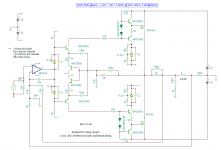
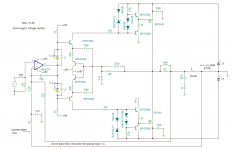
I do some change on the schematic for easier build amp and lower-saver rail voltage.
this step below used when I build or rebuild the big one, and appliable to build this small one since there are no additional problem. This small one are smaller than the small one before, only +/-25V rail.
1st->. Build the output stage (current feedback type, small DC offset still OK) and check it working or not.
2nd->. Build the input stage (place the opamp) but the current sense. Leave the current sense not connected and check it again.
3rd->. Connect all and check it.
your output stage are getting slow. your pair both are turned on in high current. you need to fasten your pair. Place 82ohm Rbe each final transistor, and double the drivers. You need to manage it from overflow.
hi. bobodioulasso,
This is the main concept. The loudspeaker itself has various impedance in various condition, specially when it placed in a box or other condition that makes some movement not caused by vouce coil force.
High damping factor power amplifier (voltage amplifier) will reduce this movement (from box reflex or neighbour loudspealer) and this partial reduction result is distortion. That mean air movement/wave (movement sum) badly distorted.
That why I'm trying to build an AC power source (VxI amplifier) but I just only reach V+I amplifier by now. VxI project stopped long time ago.
I do some change on the schematic for easier build amp and lower-saver rail voltage.
this step below used when I build or rebuild the big one, and appliable to build this small one since there are no additional problem. This small one are smaller than the small one before, only +/-25V rail.
1st->. Build the output stage (current feedback type, small DC offset still OK) and check it working or not.
2nd->. Build the input stage (place the opamp) but the current sense. Leave the current sense not connected and check it again.
3rd->. Connect all and check it.
Attachments
Last edited:
- Status
- This old topic is closed. If you want to reopen this topic, contact a moderator using the "Report Post" button.
- Home
- Amplifiers
- Solid State
- Help with this amp