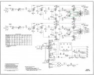
I have just done a complete overhaul on a Crown SXA amplifier. I am ready to bias the tubes however Crown used a TS-47 bulb in series with the ground to pin 8 on the EL37 output tubes. I am quite familiar with the standard bias techniques using a 1 ohm resistor and a volt meter however before I do any damage to these valuable output tubes I was hoping to get some advice on what if any resistance value is happening here with this bulb. I have measured the resistance across the existing bulbs (4 ohms) but based on the markings I cannot be sure if they are even the correct bulbs. Can I just replace this bulb with the typical 1 ohm resistor and rewire so my voltmeter reads across the resistor not in series with it as shown in the schematics when using the bias ports?
Attachments
Do you have any reason to believe they are not the originals? You can get #47 bulbs from here if you think these are not genuine: Bob's Antique Radios - Supplies
I can think of several reasons why you might not want to do this, they provide a limited amount of bias in normal operation, but will act like a fuse in the event of a bias supply failure. I suspect the amplifier is biased pretty cold based on the noted 0.5V on the EL37 cathode with the bulb in place, if the output stage is operating close to class B conditions the large increase in cathode current might cause the lamp to warm slightly reducing the maximum plate current by effectively increasing the bias.. (A swag on my part)
It is an odd arrangement for sure, but I assume this was done for a good reason.
The way this amp is designed you need to plug a milliamp meter into the jacks in series with each output tube cathode. Then adjust each output tubes bias control for the desired cathode current for each tube. It would be best to use 2 milliamp meters one for each tube because there will be some interaction between the tubes. The lamp is a ballist that is used to help stablize the bias.
Interesting setup indeed
Thank you for your quick responses. Interesting setup indeed. The lamps are mounted on the face plate. I assume they light up at some point. They do not currently light up now or when I plug in my meter which is why I think they might be incorrect. Are they there to indicate an incorrect/or correct bias situation (when lit). Wouldn't a 1% tolerance resistor be a more accurate method of controlling or "anchoring" bias. I have to admit while I know a little its these types of situations that really let me know how little.
Thank you for your quick responses. Interesting setup indeed. The lamps are mounted on the face plate. I assume they light up at some point. They do not currently light up now or when I plug in my meter which is why I think they might be incorrect. Are they there to indicate an incorrect/or correct bias situation (when lit). Wouldn't a 1% tolerance resistor be a more accurate method of controlling or "anchoring" bias. I have to admit while I know a little its these types of situations that really let me know how little.
<snip> Wouldn't a 1% tolerance resistor be a more accurate method of controlling or "anchoring" bias. <snip>
As I've indicated earlier they provide protection against bias supply failure and at high power levels they will light up - in addition they may have limited usefulness in softening initial clipping behavior.
The bias in any event is not anchored, this amplifier doesn't use regulated supplies and the operating point varies slightly with line voltage, etc.
I'd probably leave them in place..
So in this situation if I am seeing a 465 actual plate voltage. The EL37s are rated at 25 watts so if I run the tubes at %75 output should I be biasing for around 40 miliamps wth the ammeter in series connection or does this need to be calculated differnetly in this instance?
25watts/465volts= .053 * .75 = .040 amps
25watts/465volts= .053 * .75 = .040 amps
You need to figure out what bias current results in 0.5V across that lamp, that will be close to the design value, then you can decide how to trade off tube life for potential improvements in performance. It is hard to say, but I suspect this amp probably runs them at something less than 40mA each.
Not sure I understand how that is would be done across the lamp in respect to the .5 volt current. Would it be ok to leave the bulb in place and set up the jack to read across a 1 ohm resistor. It can be set up to bypass the bulb with a phono plug inserted and just bias in the more traditional method. Does the bulb effect the bias results? Should it be left in and a 1 ohm inserted in series?
I own a highly modified version of it. You set the bias by plugging an ammeter into the jacks. The 0.5 volts across the bulb is not an accurate reading but close enough to give you an idea of the current they intended.
Warm up the amp, put voltmeter across the bulb, put 2 ammeters in the 2 jacks and adjust bias pots until you get 0.5V at the bulb. Make sure currents are equal. Now read the current, that's (roughly) your target current for all future bias adjustments. Make sure you really have the correct bulb.
Warm up the amp, put voltmeter across the bulb, put 2 ammeters in the 2 jacks and adjust bias pots until you get 0.5V at the bulb. Make sure currents are equal. Now read the current, that's (roughly) your target current for all future bias adjustments. Make sure you really have the correct bulb.
Curious what you went with for you capacitor values in the power and filament supply stages. I am planning on following some advice given to me from Dennis Boyle of Chimera Laboratories. He wrote a good concise overview of the Williamson Amplifier and how to get the most out of the design. He was kind enough to look at the schematics of the SXA and give me his advice modding its unique architecture. His original post can be found here. Chimera Labs Williamson Tube Amplifier Modifications. His advice included 100-200uf at the CT and at least tripling the second and third stage power supplies. Also some advice on capacitor bypassing the cathode on the first stage tube.
I use regulated power supplies, so my capacitor values are irrelevant. That amp is dual mono but has a goofy PS setup with the PTs tied together. It's easy enough to redesign to a real dual mono power supply and you can put as much capacitance as your diodes can stand ")
As to bypassing the first cathode, what does he propose to do about the feedback connected to it?
As to bypassing the first cathode, what does he propose to do about the feedback connected to it?
Yeah the dual mono is straight forward. I have it setup so I can remove one wire to switch over once I got a final feel for my grounding/noise situation.
On that front I ditched the bus ground and ended up with a three point star ground. The first time I fired up the amp in this configuration it was so quiet I thought something must be wrong. I grounded the left and right channel power supply capacitors, heaters, bias, and and transformer grounds to the left and right lugs of the can capacitors (closet to transformers). Everything else went to ground at the center point ground where the original inputs are grounded. I swapped out the phono ins for RCAs and ran a shielded wire for the positive hookup. Grounding the shield to the center low level star ground point killed the last little remnants of noise. The best configuration I found here was attaching a wire to the shield at the rca end and braiding the positive input / negative input and shield return wires together and attaching the negative input and shield to the low level star ground.
I initially replaced the cans with some electrolytics I had lying around. Waiting on two F&T dual 100uf cans as replacements for PT and AF/Phase Inv stages. I know the purists might shutter here but the F&T's seem to enjoy a bit of a better reputation. I should have pulled the trigger on the Mudorf M-Lytics but I chickened out at the last minute. I will add some additional caps sub chassis for the driver stage. I plan on bypassing these with some .01uf film and foils down the road.
I went with Rel multicaps RTX's for coupling. .1uf and .47
As far as the bypass situation and its effect on the negative feedback loop he made no mention of that being an issue. I will have to mention it to him. I am glad you mentioned it.
Just to clarify the first cathode bypass. Boyle recommended running a 100 - 470 uf capacitor in parallel with the 2200 ohm resistor (R10,R25).
Yes I got that. Do you (or he) understand that doing so will kill the NFB?
- Status
- This old topic is closed. If you want to reopen this topic, contact a moderator using the "Report Post" button.
- Home
- Amplifiers
- Tubes / Valves
- Help with odd bias method on Crown tube amp