Agreed. Sreten rings the bell of reality as alwaysDon't feel forced to immediately go down the measurement route. My first design was by simulation methods and it came out very close to the measured result so quite reliable as long as it is done methodically using reliable inputs under known measurement conditions.
I will learn more about simulating, these links are very interesting ive just ordered some different resistors i believe i can get a good sound out of this x-over before i find a better design.
I won't get the ClarityCaps for the woofer next time, apparently they don't make any difference on woofers. Would you recommend using ClarityCaps for the tweeter or go with Jantzen Audio, i believe resistors and inductors won't make much difference too, it's all about the design.
I don't think I'd hear the difference in either brand personally - but I've never done a comparison either lol.
I think a good starting point for caps is those with a polypropylene dielectric with at least 50v power handling (feel free to correct me). Getting the right value is the key.
Components in series with the drivers are far more important than those in parallel. Those in parallel "wick away" unwanted energy - so the quality of their treatment to the signal is less important. Parallel components may still need to handle power - all dependent on the load presented across the circuit at a given frequency.
I don't like quoting other designers since I'm putting words in their mouths. I've read reputable designers that would - if they deemed it measureable or noticeable throw money into esoteric components, but they choose iron core inductors for large values (instead of large gauge air core) because of lower resistance and the inductors do not impart a significantly measureable or audible change.
with simulation - if your component values change and you are able to improve the response - I would start with a vanilla polypropolene capacitor - infact spend your money to get a range of values shipped (rather than spending all your money on the "perfect" value). Then you can tweak and see if small variations improve or not (since you will have a good inventory - something I need to build up myself).
Wow incredible design, love the bracing system, thicker baffle and tweeter positioning, i'd expect with the tweeter having no sidewalls the same distance from the edge helps with diffraction.
I wished i had better bracing from the start.
this is a full simulation design, although I did model enclosures based on measured broken in T/S params of the actual drivers being used. Funnily enough as Vance Dickason suggested, T/S params will be different and will change - but the relationships between T/S params that drive enclosure parameters do not - so that measuring your own after break in doesn't really affect the enclosure design based on manufacturer specs. In my limited experience this is true.
Thanks dave, i too don't think i'd hear the difference in either brand of caps but i just wanted to 'tick all boxes' approach and now realise its impossible to achieve lol.
Yes i've read caps dont need to be more than 50V so theses big 1200V Jantzen are unnecessary. I've ordered three higher ohm resistors (1.8, 2.2 and 3 ohms) to replace the 1.5 Ohm in series of the tweeter, just to learn the differences, besides resistors cost peanuts.
I think getting a range of values is the best approach with the caps too so i can then tweak it slightly.
Thanks dave, i too don't think i'd hear the difference in either brand of caps but i just wanted to 'tick all boxes' approach and now realise its impossible to achieve lol.
Yes i've read caps dont need to be more than 50V so theses big 1200V Jantzen are unnecessary. I've ordered three higher ohm resistors (1.8, 2.2 and 3 ohms) to replace the 1.5 Ohm in series of the tweeter, just to learn the differences, besides resistors cost peanuts.
I think getting a range of values is the best approach with the caps too so i can then tweak it slightly.
That's right - those resistor values for example are useful since you can series them to make even larger values. I've found you have to go "too far" in one direction to realise then come back to a happy medium.
That's right - those resistor values for example are useful since you can series them to make even larger values. I've found you have to go "too far" in one direction to realise then come back to a happy medium.
I didn't think about series them to make larger values, thanks for pointing that out. Its like the wadding test i did "too much" then down to a happy medium, same as the port tuning too.
I didn't think about series them to make larger values, thanks for pointing that out. Its like the wadding test i did "too much" then down to a happy medium, same as the port tuning too.
Yes - resistors and inductors are additive in series. Caps are additive in parallel (loosely speaking) so same can be done for those components.
The downside with series inductors to increase inductance is ever increasing DC resistance which will have an unwanted side-effect. For modeling purposes this isn't a problem, but testing in the real world you need to account for it.
Thanks again for the advice i respect i have so much to learn on x-overs, and respect how much knowledge you people have in loudspeaker building.
I can understand if my inductors are wrong to start with then its going to be difficult to get the best results.
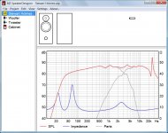
Am interested to see the differences in the resistors ive ordered just to make them more audible for now, i think it has a peak around 4khz which makes them a bit sibilance (issy on the female vocals in particular). And compared to my friends dxt's (i know room acoustics and baffle etc play a major part) they sound like they have more clarity and sparkle above 7khz, which i quite like.
Am interested to see the differences in the resistors ive ordered just to make them more audible for now
If you swap two capacitors as well, the speaker should get quite audible for the moment.
Attachments
If you swap two capacitors as well, the speaker should get quite audible for the moment.
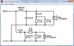
Thanks Dissi, i see you have changed C1 tweeter cap from 9uF to 4.5uF, that 9uF comes from two 4.5uF, if i take the one 4.5uF out and put a 3 ohm resistor in series like you've done do u think it will benifit?
Yes, but use that 4.5 uF capacitor to increase the C of the zobel to 9 uF. Due to this modification the frequency response gets more or less flat above 300 Hz, at least in the simulation.
Ah i see now great i'll give it go and let you know how its sounds
Hi, i could do with some advice, i've been reading the link from fatmarley on 'introduction to crossovers without measurements' and got a bit stuck. When flattening my woofers impedance by multiplying the rdc (5.9ohm) by 1.25 i get 7.375.
Can i put two resistors with different values there?
The hand written schematics from the guy at my current x/o supplier, has 7.5 ohm written next to this resistor then in brackets writes x2 15 ohm in parallel, is this because he may of adjusted them later? Thanks guys.
Can i put two resistors with different values there?
The hand written schematics from the guy at my current x/o supplier, has 7.5 ohm written next to this resistor then in brackets writes x2 15 ohm in parallel, is this because he may of adjusted them later? Thanks guys.
The hand written schematics from the guy at my current x/o supplier, has 7.5 ohm written next to this resistor then in brackets writes x2 15 ohm in parallel, is this because he may of adjusted them later? Thanks guys.
This is done mostly to increase the power handling of the resistor.
This is done mostly to increase the power handling of the resistor.
Thank you so does the value not have to be doubled? Do you know if i can use different values in parallel? Example: 2.4 Ohm + 5.0 Ohm = 7.4 Ohm
I know I can put different value caps in parallel but not sure about resistors.
Thanks in advance.
Thank you so does the value not have to be doubled? Do you know if i can use different values in parallel? Example: 2.4 Ohm + 5.0 Ohm = 7.4 Ohm
I know I can put different value caps in parallel but not sure about resistors.
Thanks in advance.
The values decrease in parallel (a 2.4 in parallel with a 5 would be like 1.6 ohms), but yes you could.
Yes, but use that 4.5 uF capacitor to increase the C of the zobel to 9 uF. Due to this modification the frequency response gets more or less flat above 300 Hz, at least in the simulation.
Sorry the schematics are different from the actual crossover:
The 9uF cap on the tweeter consists of a 5uF and a 4uF.
The 4.5uF cap on the woofer is acually 4.4uF (x2 2.2uF).
Am i right in thinking i should swap the 5uF cap from the tweeter in parallel with 4.4uF on the woofer.
You'd of never of thought I waited over four months for these x/o's from the suppliers and a month after that too get the schematics.
cheers.- Status
- This old topic is closed. If you want to reopen this topic, contact a moderator using the "Report Post" button.
- Home
- Loudspeakers
- Multi-Way
- Help with my 1st project a 2-way with Seas drivers