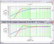
zeljkor said:I will drive 416 with 6080 SE amplifier. Room size is something like 3.6meters x 5 meters. Because of furniture configuration (and wife) I will put boxes 60 centimeters from back wall - smaller one (possible in corners also). I would like to achieve F3 of at least 35Hz if possible and I will cross it around 400-500Hz.
Zeljko
OK, with no appreciable room gain above ~34 Hz and ~2 ft away from the walls combined with a low power SE amp, a tuning around 1.6x Fs is desirable, i.e. a typical '40s - early '50s Altec cab alignment except stretched into a MLTL, so the original Iconic's 25.5" external width and ~8 ft^3 net would be the minimum IMO to start with and if you want an in-room 35 Hz F3, then your amp will in theory have to have a very high output impedance driving a much larger cab tuned to Fs if not backed up against a strong wall.
GM
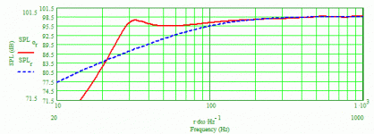
Doing just that, making the width 25" (and keeping the depth at 25") results in the attached response. Doesn't look very pretty, does it? Basically in this immense cabinet it's difficult to get a tuning that results in not only a lower F3 but and overall good response.
zeljkor said:No. Let depth stays at 25". I would like to try to increase volume. This is just to see what will happen, maybe we can go little lower with F3 (just curious)
Attachments
Re: An enlarged ML-TL
I'm curious why you spec such high stuffing densities since one of the advantages of the MLTL is damping the vent enough to minimize it.
Regardless, for mating to typical horns a very wide BW woofer is required and high stuffing densities will tend to damp them too much, making for a tonally unbalanced response through the XO BW. Now if a Dr. Geddes's style foam plug is used in the horn, then either damping this HF BW down or using a much flatter response woofer is desirable.
GM
pkitt said:.........increased the stuffing density to 1 lb/cu.ft..........
I'm curious why you spec such high stuffing densities since one of the advantages of the MLTL is damping the vent enough to minimize it.
Regardless, for mating to typical horns a very wide BW woofer is required and high stuffing densities will tend to damp them too much, making for a tonally unbalanced response through the XO BW. Now if a Dr. Geddes's style foam plug is used in the horn, then either damping this HF BW down or using a much flatter response woofer is desirable.
GM
pkitt said:Doesn't look very pretty, does it?
I assume you haven't taken into account any of the SE amp's output impedance which will increase the driver's effective Qts, 'filling up' the cab. At minimum, a SE amp will have around 2.2 - 2.5 ohms resistance, but ideally the actual spec is required to optimize the cab's alignment.
GM
Re: Re: An enlarged ML-TL
I tend to use stuffing densities in ML-TLs higher than what many others use because I'm willing to trade off a bit of bass response in order to minimize the ripples in the response above a couple-hundred Hz or so, and also because my designs are often 3-ways with the woofer crossing at higher frequencies to dome midranges and I want the woofer's TL response to smoothly integrate with that of the midrange. I don't have any experience (or interest in) mating a woofer with a horn, and if what I offer here is inappropriate for a specific case, then I hope you and others will be able and willing to offer insight and not let me lead another hobbyist down the wrong path. Nevertheless, for my uses, I don't buy into a generalized statement that says something like, "using stuffing densities higher than X lb/cu.ft. indicates something is wrong with the ML-TL design in the first place", as I've seen stated by a person or two on this and other forums.
I tend to use stuffing densities in ML-TLs higher than what many others use because I'm willing to trade off a bit of bass response in order to minimize the ripples in the response above a couple-hundred Hz or so, and also because my designs are often 3-ways with the woofer crossing at higher frequencies to dome midranges and I want the woofer's TL response to smoothly integrate with that of the midrange. I don't have any experience (or interest in) mating a woofer with a horn, and if what I offer here is inappropriate for a specific case, then I hope you and others will be able and willing to offer insight and not let me lead another hobbyist down the wrong path. Nevertheless, for my uses, I don't buy into a generalized statement that says something like, "using stuffing densities higher than X lb/cu.ft. indicates something is wrong with the ML-TL design in the first place", as I've seen stated by a person or two on this and other forums.
GM said:
I'm curious why you spec such high stuffing densities since one of the advantages of the MLTL is damping the vent enough to minimize it.
Regardless, for mating to typical horns a very wide BW woofer is required and high stuffing densities will tend to damp them too much, making for a tonally unbalanced response through the XO BW. Now if a Dr. Geddes's style foam plug is used in the horn, then either damping this HF BW down or using a much flatter response woofer is desirable.
GM
Hi GM!
Thanks for helping Unfortunatelly it is hard to tell output impedance since I did not make or design this amp. Anyway it is parafeed circuit (ZenMod explained me this) where constant current source is in anode circuit and transformer is coupled to tube by capacitor so no DC component goes to transformer.
Thanks for helping
With half as much stuffing...
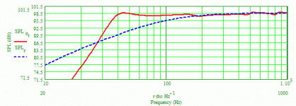
In the larger ML-TL version (15"W x 25"D), here's the attachment shows the system response with a stuffing density of 0.5 lb/cu.ft. (and no other changes). There's a bit more ripple in the response but it's not much more and is entirely satisfactory.
In the larger ML-TL version (15"W x 25"D), here's the attachment shows the system response with a stuffing density of 0.5 lb/cu.ft. (and no other changes). There's a bit more ripple in the response but it's not much more and is entirely satisfactory.
zeljkor said:Hi guys,
what is then final conclusion ? It this then too much stuffing? Very soon I will begin to build midrange Edgar horn after that MLTL cabinet goes in productionSo there is enough time to find optimal solution.
Thanks!
Attachments
Re: An enlarged ML-TL
OK.
I thought that's what I did, at least that was my intention.
OK, like it or not, high stuffing densities in a MLTL implies a cover up of sorts to me and some others and because the extra design flexibility beyond using just a golden or acoustic ratio is available, where practical we prefer to design to minimum stuffing densities required with the understanding that the sims tend to overstate the measured response and that a measured +/- a dB or two is inaudible regardless of whether it's in the XO BW or not.
Regardless of our design preferences for our personal use though, I learned early on from folks building my 'FR' driver and woofer/mid-bass designs for mating to HF horns that where I spec'd higher stuffing densities of up to 0.5 lbs/ft^3 they for the most part wound up tearing most of it out before they were happy with its performance, so now only post sims with minimal damping (typically 0.2 lbs/ft^3 which as best I can figure equates to the old standard of lining one wall, top and back with either Celotex or 1" acoustic fiberglass) and let the 'customer' decide if the design works for them or willing to accept more stuffing to change the baffle layout/whatever to get a similar or smoother response.
Obviously, it's up to the 'customer' to find the right amount of damping, but I believe those of us with the software/experience should design the smoothest response we can using minimal damping based on their criteria and post this as a 'worst case' with a note that more damping placed at such n' such points will smooth it out if the actual response in-room sounds too distorted due to excessive vent output at/below tuning and/or its harmonics are audibly comb filtering with the mids, HF, 'smearing' them.
GM
pkitt said:I tend to use stuffing densities in ML-TLs higher than what many others use because I'm willing to trade off a bit of bass response in order to minimize the ripples in the response above a couple-hundred Hz or so............
...........if what I offer here is inappropriate for a specific case, then I hope you and others will be able and willing to offer insight and not let me lead another hobbyist down the wrong path.
Nevertheless, for my uses, I don't buy into a generalized statement that says something like, "using stuffing densities higher than X lb/cu.ft. indicates something is wrong with the ML-TL design in the first place".............
OK.
I thought that's what I did, at least that was my intention.
OK, like it or not, high stuffing densities in a MLTL implies a cover up of sorts to me and some others and because the extra design flexibility beyond using just a golden or acoustic ratio is available, where practical we prefer to design to minimum stuffing densities required with the understanding that the sims tend to overstate the measured response and that a measured +/- a dB or two is inaudible regardless of whether it's in the XO BW or not.
Regardless of our design preferences for our personal use though, I learned early on from folks building my 'FR' driver and woofer/mid-bass designs for mating to HF horns that where I spec'd higher stuffing densities of up to 0.5 lbs/ft^3 they for the most part wound up tearing most of it out before they were happy with its performance, so now only post sims with minimal damping (typically 0.2 lbs/ft^3 which as best I can figure equates to the old standard of lining one wall, top and back with either Celotex or 1" acoustic fiberglass) and let the 'customer' decide if the design works for them or willing to accept more stuffing to change the baffle layout/whatever to get a similar or smoother response.
Obviously, it's up to the 'customer' to find the right amount of damping, but I believe those of us with the software/experience should design the smoothest response we can using minimal damping based on their criteria and post this as a 'worst case' with a note that more damping placed at such n' such points will smooth it out if the actual response in-room sounds too distorted due to excessive vent output at/below tuning and/or its harmonics are audibly comb filtering with the mids, HF, 'smearing' them.
GM
zeljkor said:Hi GM!
Thanks for helping..........
Greets!
You're welcome!
Unfortunately, I'm not amp design savvy enough to know if this tells me anything about its damping factor (DF) that would in turn tell us its output impedance, so all I can say is that if the cab is designed as maximally flat using 2.5 ohms and it turns out to be higher, then its LF response will suffer in some way or other, though whether it might/will be objectionable to you I can't say.
Indeed, some prefer the vintage LF 'bloom' it provides and may even blend in to the room's gain curve better, but for those of us who prefer an accurate reproduction it's downright obnoxious unless tuned much lower to 'bleed off' its excessive/'loose' mid-bass.
Then again, designing to a lower DF means an even larger cab, so if that's not an option, then experimenting with vent tuning/damping is all you can do.
GM
Re: Re: An enlarged ML-TL
I assume you saw my post above with the results from using half as much stuffing density (even though it's still way too high according to your experience). To be frank, the response with this lighter stuffing does look better in some ways. I have always tried and will continue to do so to keep the response ripples under +/-1 dB, maybe even lower, for my personal use and for others who ask me for modeling help. I'm usually working with woofers and midwoofers that have pretty low Fs and higher Qts, which allows me to get both a satisfactory F3 along with a nicely smooth overall response. With the drivers I usually work with (not at all like this GPA woofer) I can't begin to imagine wanting to build a design that ended up with a stuffing density of 0.2 or less as I know its response would be really ragged and ugly. Okay, we have different design goals and whomever may want to use them will have to decide on their own which to use.
I assume you saw my post above with the results from using half as much stuffing density (even though it's still way too high according to your experience). To be frank, the response with this lighter stuffing does look better in some ways. I have always tried and will continue to do so to keep the response ripples under +/-1 dB, maybe even lower, for my personal use and for others who ask me for modeling help. I'm usually working with woofers and midwoofers that have pretty low Fs and higher Qts, which allows me to get both a satisfactory F3 along with a nicely smooth overall response. With the drivers I usually work with (not at all like this GPA woofer) I can't begin to imagine wanting to build a design that ended up with a stuffing density of 0.2 or less as I know its response would be really ragged and ugly. Okay, we have different design goals and whomever may want to use them will have to decide on their own which to use.
GM said:
OK.
I thought that's what I did, at least that was my intention.
OK, like it or not, high stuffing densities in a MLTL implies a cover up of sorts to me and some others and because the extra design flexibility beyond using just a golden or acoustic ratio is available, where practical we prefer to design to minimum stuffing densities required with the understanding that the sims tend to overstate the measured response and that a measured +/- a dB or two is inaudible regardless of whether it's in the XO BW or not.
Regardless of our design preferences for our personal use though, I learned early on from folks building my 'FR' driver and woofer/mid-bass designs for mating to HF horns that where I spec'd higher stuffing densities of up to 0.5 lbs/ft^3 they for the most part wound up tearing most of it out before they were happy with its performance, so now only post sims with minimal damping (typically 0.2 lbs/ft^3 which as best I can figure equates to the old standard of lining one wall, top and back with either Celotex or 1" acoustic fiberglass) and let the 'customer' decide if the design works for them or willing to accept more stuffing to change the baffle layout/whatever to get a similar or smoother response.
Obviously, it's up to the 'customer' to find the right amount of damping, but I believe those of us with the software/experience should design the smoothest response we can using minimal damping based on their criteria and post this as a 'worst case' with a note that more damping placed at such n' such points will smooth it out if the actual response in-room sounds too distorted due to excessive vent output at/below tuning and/or its harmonics are audibly comb filtering with the mids, HF, 'smearing' them.
GM
At 0.2 lb/cu.ft, FWIW
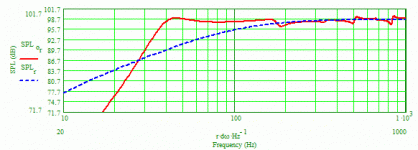
Modeling the 15" x 25" cabinet again but with a stuffing density of 0.2 lb/cu.ft., the attachment shows the system response. Clearly the magntitudes of the ups and down are bigger, some more than I would care to know exist, but will they be audible? Don't know, but I've now offered the OP three different stuffing density choices in the larger cabinet, all of which have an F3 of ~35-37 Hz.
GM: If you're ever in the neighborhood of Columbus, Ohio, you're more than welcome to stop by my house to listen to my over-stuffed t-lines and make your own judgement as to their sounds.
Attachments
Re: Re: Re: An enlarged ML-TL
Yes, I did.
Laudable goal, now if only us humans had the ability to hear how good it is down in the LF/mid-bass BW...........
GM
pkitt said:I assume you saw my post above with the results from using half as much stuffing density........
I have always tried and will continue to do so to keep the response ripples under +/-1 dB, maybe even lower, for my personal use and for others who ask me for modeling help.
Yes, I did.
Laudable goal, now if only us humans had the ability to hear how good it is down in the LF/mid-bass BW...........
GM
Re: At 0.2 lb/cu.ft, FWIW
Thanks for the offer and if I can ever get my Altec MLTL system back up to 'snuff' and you happen to be down 'Hotlanta' way you're welcome to come experience how good minimally damped MLTLs loaded with ultra wide BW woofers can sound.
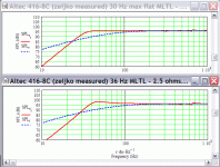
Anyway, here's my take on it based on an assumed 2.5 ohms of output impedance which is close to the size you simmed and a 42" o.d. height since it's a popular one among the Altec faithful, including me .
.
Obligatory max flat 30 Hz Fb alignment (upper sim):
L = 40.5"
CSA = 385.75"^2 (recommend 25.5" W x 15.43" D)
zdriver = 18.71" (simmed, but end loaded is almost as smooth)
zport = 37"
dport = 6" (28.274"^2)
Lport = 2"
density = 0.2 lbs/ft^3 from the top down 29.68"
Vintage 36 Hz alignment (lower sim):
L = 40.5"
CSA = 385.75"^2 (recommend 25.5" W x 15.43" D)
zdriver = 18.71" (simmed, but end loaded is almost as smooth)
zport = 36"
dport = 7" (38.485"^2)
Lport = 2"
density = 0.2 lbs/ft^3 from the top down 28.68"
All dims inside (i.d.) and approximate and up to a point, retuning the vent can adjust for different output impedances, so I recommend a removable port baffle in case you need to use a different port area.
GM
pkitt said:
GM: If you're ever in the neighborhood of Columbus, Ohio, you're more than welcome to stop by my house to listen to my over-stuffed t-lines and make your own judgement as to their sounds.
Thanks for the offer and if I can ever get my Altec MLTL system back up to 'snuff' and you happen to be down 'Hotlanta' way you're welcome to come experience how good minimally damped MLTLs loaded with ultra wide BW woofers can sound.
Anyway, here's my take on it based on an assumed 2.5 ohms of output impedance which is close to the size you simmed and a 42" o.d. height since it's a popular one among the Altec faithful, including me
Obligatory max flat 30 Hz Fb alignment (upper sim):
L = 40.5"
CSA = 385.75"^2 (recommend 25.5" W x 15.43" D)
zdriver = 18.71" (simmed, but end loaded is almost as smooth)
zport = 37"
dport = 6" (28.274"^2)
Lport = 2"
density = 0.2 lbs/ft^3 from the top down 29.68"
Vintage 36 Hz alignment (lower sim):
L = 40.5"
CSA = 385.75"^2 (recommend 25.5" W x 15.43" D)
zdriver = 18.71" (simmed, but end loaded is almost as smooth)
zport = 36"
dport = 7" (38.485"^2)
Lport = 2"
density = 0.2 lbs/ft^3 from the top down 28.68"
All dims inside (i.d.) and approximate and up to a point, retuning the vent can adjust for different output impedances, so I recommend a removable port baffle in case you need to use a different port area.
GM
Attachments
Pay really close attention to GM's graphs
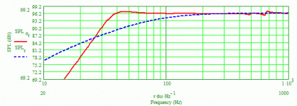
While both examples are probably very good designs, you'll note that the Y-axis (for dB SPL) covers a range of 50 dB, whereas on my graphs the Y-axis has much better resolution because it covers only 30 dB. Thus, the responses in GM's graphs look alot smoother than they really are. GM is using, I believe, Martin King's older software that didn't allow changing/customizing the axes, whereas I'm using his latest software that does. I always prefer to publish these SPL graphs so that it's easy to see the F3 and F6 points from the vertical axis being 3 dB/division. I seriously doubt there will be any audible differences between my designs with 0.5 or 0.2 lb/cu.ft. stuffing density and either of these latest GM designs. Your choice, of course.
While both examples are probably very good designs, you'll note that the Y-axis (for dB SPL) covers a range of 50 dB, whereas on my graphs the Y-axis has much better resolution because it covers only 30 dB. Thus, the responses in GM's graphs look alot smoother than they really are. GM is using, I believe, Martin King's older software that didn't allow changing/customizing the axes, whereas I'm using his latest software that does. I always prefer to publish these SPL graphs so that it's easy to see the F3 and F6 points from the vertical axis being 3 dB/division. I seriously doubt there will be any audible differences between my designs with 0.5 or 0.2 lb/cu.ft. stuffing density and either of these latest GM designs. Your choice, of course.
zeljkor said:Hi GM,
these graphs are excellent. I think I will choose the first option for buildingJust to be sure these cabinet dimensions are inner dimensions or I am wrong?
Thanks,
Zeljko
Re: Re: At 0.2 lb/cu.ft, FWIW
And by 'approximate', I mean I just punch numbers into an Excel SS and post the results, so rounding up numbers to the nearest easy to measure fraction, decimal point or metric conversion is fine.
Anyway, hope you update us with some pictures and your thoughts on the performance of whatever in-room alignment you wind up with.
GM
GM said:
Greets!
All dims inside (i.d.) and approximate.......
And by 'approximate', I mean I just punch numbers into an Excel SS and post the results, so rounding up numbers to the nearest easy to measure fraction, decimal point or metric conversion is fine.
Anyway, hope you update us with some pictures and your thoughts on the performance of whatever in-room alignment you wind up with.
GM
pkitt said:........whereas on my graphs the Y-axis has much better resolution........
I used the most recent vented box WS, but didn't notice your plot's finer resolution until I did my sims and wondered why mine were so much smoother. I'm a firm believer in comparing 'apples to apples', but was too preoccupied/tired last night to want to mess with MathCad to see if I could change mine to match yours and if not, ask you to post sims.
Anyway, thanks for pointing out the option to change them, wish I'd known it sooner.............
Plots using your scale. Note that unless MJK revised his plot calculation with these newer WSs, the BW above 500 Hz is increasingly inaccurate, but I can't recall now if he said in a good or bad way.
GM
Attachments
For a little bit better picture...
I modeled your first example (the flat 30-Hz one) and the attachment has a better picture. In all of the other modeling and graphs I did in this thread, I arbitrarily modeled with just 0.5 ohms in series, but used 2.5 ohms for this one to match your results. If I were to suggest an improvement, it would be to lengthen the port to 2.5" which will get rid of the slight rise in output as the knee in the response curve is approached making the overall response truly flat.
Edit: Never mind, I forgot what I wanted to say.
Edit No. 2: I guess what I wanted to say was that your response is smoother than what I achieved for the same 0.2 stuffing density and I was wondering if that was a result of your placing the driver and port closer to each other than I? I always try, at least as a starting point, placing the driver at 20% of the line's length from its beginning, which often is pretty much the best place, then manipulating the port's location somewhat, and its dimensions, to get an acceptable response.
GM said:
I used the most recent vented box WS, but didn't notice your plot's finer resolution until I did my sims and wondered why mine were so much smoother. I'm a firm believer in comparing 'apples to apples', but was too preoccupied/tired last night to want to mess with MathCad to see if I could change mine to match yours and if not, ask you to post sims.
Anyway, thanks for pointing out the option to change them, wish I'd known it sooner.............
Plots using your scale. Note that unless MJK revised his plot calculation with these newer WSs, the BW above 500 Hz is increasingly inaccurate, but I can't recall now if he said in a good or bad way.
GM
Attachments
- Status
- This old topic is closed. If you want to reopen this topic, contact a moderator using the "Report Post" button.
- Home
- Loudspeakers
- Multi-Way
- Help with MLTL design for GPA416-8c
