The main document never does specify what the exact use is. Since I most likley won't have the volume past 50% 2.2uF would give me around 100ms for the input. 22uf as said also gives me aorund 100ms at the output...
With active filtering can the passive filters be eliminated? Thanks for the education on how this better works. All caps are going to be poly film and resistors metal oxide 1%
In my version I removed the Q/Boost and the 4th order. I have 2 saleen key butterworth's. 40HZ High Pass and Variable Low Pass being fed into the phase adjustment. Any other recomended tips or tweaks? I am going to have a PCB made so I want to make sure I iron out all the "bugs".
This pre-amp is going to be installed into a Klipsch dual 6" sub using the stock class G? amplifier. The input is going to be from the LFE output on my Yamaha 6.1 RX. The sub has very good sound from about 35-180HZ. Insted of trash I decided to DIY it into a small HT sub and learn a few things on the way.
The 5 3ohm stable 160W A/B amp boards inside also make for a nice 5.1 AMP but thats the next project.")
With active filtering can the passive filters be eliminated? Thanks for the education on how this better works. All caps are going to be poly film and resistors metal oxide 1%
In my version I removed the Q/Boost and the 4th order. I have 2 saleen key butterworth's. 40HZ High Pass and Variable Low Pass being fed into the phase adjustment. Any other recomended tips or tweaks? I am going to have a PCB made so I want to make sure I iron out all the "bugs".
This pre-amp is going to be installed into a Klipsch dual 6" sub using the stock class G? amplifier. The input is going to be from the LFE output on my Yamaha 6.1 RX. The sub has very good sound from about 35-180HZ. Insted of trash I decided to DIY it into a small HT sub and learn a few things on the way.
The 5 3ohm stable 160W A/B amp boards inside also make for a nice 5.1 AMP but thats the next project.
Here is what I have for the PCB
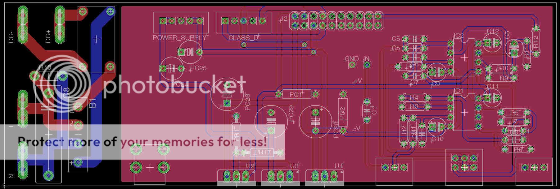
The left side is the mains input. The center is the voltage regs for the amps and preamp. The right side is the audio filter.
Please have a look and comment. All connections are matched to the origional design to make it plug and play friendly. It is very similar to the origional PCB with the only differences being the fuse is going to be external and the filter is for the subwoofer only. The power plug was hard wired. I opted to use a switched and fused 3-prong socket to make it more like a standard sub.
I am still unsure that I am using the best filter design so please comment on that also. AndrewT pointed out some design issues that I have worked on but if there is a better proved design I can easily update the schematic and board.
The input voltage is +-33V from the SMPS. The regulated volatges are +-15V and + 20V
The amp voltage is variable 0-60V and controlled by the BASH circiut using amp level feedback.
The amp is a linear full bridge I believe in class A/B with an opamp feedback to the power supply which runs in class D or G?
Thanks for all the help. This has been a very fun project so far.
Last edited:
- Status
- This old topic is closed. If you want to reopen this topic, contact a moderator using the "Report Post" button.