I've been reading up and doing some breadboard experiments on basic amp designs. One of the things that I'm surprised at is the use of two transistors or op-amps per channel. My question is: If I bias the ac signal going into the transistor so that 0v is now the middle of the transistors operating range... wouldn't that give me the amplification I need? Then I would just need to take the DC bias back out of the signal on the other side of the transistor--which I think should be able to be done with a capacitor.
I've been trying to start with a "simple" amp circuit and work my way up. But a lot of sites talk about chip-amps which I want to avoid until I understand the basic circuits first. So I've been trying to design a basic circuit with just a transistor or even a LM741 as a amp.
This is almost another thread, but where I think I'm messing up (one of many areas I'm sure!) is that idea of impedance on the input/output. I think my simple circuits I've been building have the impedance all out of whack. I don't see that parameter (impedance input, and impedance output) on most data sheets though. Is it called something else?
Thanks for helping the new guy out!!!")
I've been trying to start with a "simple" amp circuit and work my way up. But a lot of sites talk about chip-amps which I want to avoid until I understand the basic circuits first. So I've been trying to design a basic circuit with just a transistor or even a LM741 as a amp.
This is almost another thread, but where I think I'm messing up (one of many areas I'm sure!) is that idea of impedance on the input/output. I think my simple circuits I've been building have the impedance all out of whack. I don't see that parameter (impedance input, and impedance output) on most data sheets though. Is it called something else?
Thanks for helping the new guy out!!!
Maybe post the circuit you are working with ?
Have a read at all this thread which got on to opamps as well,
http://www.diyaudio.com/forums/analog-line-level/161004-basic-common-emitter-amp-help.html
and this one,
http://www.diyaudio.com/forums/anal...ow-derermine-optimum-bias-resistor-value.html
Have a read at all this thread which got on to opamps as well,
http://www.diyaudio.com/forums/analog-line-level/161004-basic-common-emitter-amp-help.html
and this one,
http://www.diyaudio.com/forums/anal...ow-derermine-optimum-bias-resistor-value.html
Last edited:
Look up the Common Collector and common Emitter amplifier.
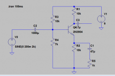
thanks for the suggestions guys, but I'm still having no luck. Attached you'll find a circuit I ran in LTSPICE and it appears to work. However I have this on my bench and I'm getting nada, nothing, zip... hopefully someone will give me a hand.
I have a scope and I see the DC biased signal on the base pin of my NPN. So I know I'm good to that point. But the collector is a flat line...
If you ask why my Caps are so high value... weird thing. If I just connect my music source to a cap then my speaker to the other side of the cap (connecting the grounds together, if I use .1U or .22U or .47U capacitors no sounds come through. If I use these "big" 1000U caps, I hear music. Weird, I'd think the larger the Farad value the more it would distort and "flatten" out the music.... Anyway. That's a secondary question I guess.
thanks for any help. I'm having so much trouble with this simple amp...
Attachments
You mention connecting a speaker...
Not sure what you are trying to do here. This amp won't drive a speaker at all and it would struggle with headphones. R1 limits the current that can flow.
Also, as a speaker is low impedance that is why you need a large value cap to "allow" the audio through (if you are connecting a cap in series with a speaker).
I don't know why the simulator shows your circuit to be working.
Let's do it long hand.
The total resistance R1 through to R2 is 20k. Assume Q4 has 1Vce.
Then the collector current is ~ {9-1} / 20k ~ 0.4mA
The emitter of Q4 will be sitting at ~4V
The input base bias sets the bias voltage to ~ 7/{10+7}*9 ~ 3.7V
The be junction of Q4 is reverse biased, i.e. switched OFF.
Can anyone with simulator experience explain what the simulator has set up to allow it to show a working amplifier?
I don't know why the simulator shows your circuit to be working.
Let's do it long hand.
The total resistance R1 through to R2 is 20k. Assume Q4 has 1Vce.
Then the collector current is ~ {9-1} / 20k ~ 0.4mA
The emitter of Q4 will be sitting at ~4V
The input base bias sets the bias voltage to ~ 7/{10+7}*9 ~ 3.7V
The be junction of Q4 is reverse biased, i.e. switched OFF.
Can anyone with simulator experience explain what the simulator has set up to allow it to show a working amplifier?
I didn't see anything wrong with the basic circuit so I'll work it out my way and see if we get the same answers.
Vb is approx 9/(10K+7K)*7K which is 3.7 volts.
Ie is 3.0/10K which is 0.37 ma. (The 3.0 is Vb less 0.7 volts)
Ib is small and hfe dependent and so I'm going to discount it and say Ic = Ie. So that gives 3.0 volts across the collector load resistor.
Does the amp work... yes, but as I mentioned earlier it has no real drive capability.
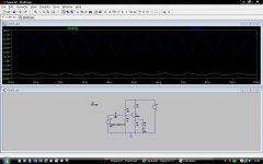
Next I'll so a Spice simulation and see (lol, can't believe I'm saying that).
And it seems OK
Vc is 5.9
Vb is 3.7
Ve is 3.07
Edit... top blue trace is collector volts, green trace is Vin
Attachments
Last edited:
Hi,
I wanted to start from the input bias end, and when I started it predicted such a low emitter current (310uA) that I thought I had better check what the maximum collector current could be (400uA).
That's where this circuit comes unstuck.
It is trying to operate at a tiny emitter current and with an output impedance of ~10k cannot sensibly drive any load.
It desperately needs a buffer stage.
You mention connecting a speaker...
Not sure what you are trying to do here. This amp won't drive a speaker at all and it would struggle with headphones. R1 limits the current that can flow.
Also, as a speaker is low impedance that is why you need a large value cap to "allow" the audio through (if you are connecting a cap in series with a speaker).
Folks, thanks for the continued support!! I guess I need to give some more detail. What I'm trying to do is learn a bit about amps and build a few small circuits. This is my first attempt. I'm trying to take the signal from an old blackberry and play it through an old speaker I have. NOTE: if I connect the phone *directly* to the speaker, it works fine and sounds fine. Of course, it isn't real loud, but it plays and all is well. So I'm just trying to build a simple amp and witness that the speaker plays a bit louder... Nothing fancy just witness that my amp does actually amplify. The speaker is a 3ohm load, that could be a problem?
A lot of you put a ton of equations into your response I guess I need a bit of help understanding how to apply that knowledge into my particular issue. Someone mentioned I need a buffer, does anyone have a *very* basic buffer circuit they can link to that I could add to this amp? I guess I could jump right to chip-amp but I'd really like to understand what's happening more. I get the idea from the other posts that I don't have enough current flowing? Should I just lower the value of all my resistors in proportion? Say divide them all by 10; or 100?
Houston we have a problem...
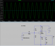
I'm digging around a bit more and on my sim I added a 3 ohm load to act like my speaker. My amplification went to almost a flat line. I'd say that's "bad"
Why does the phone work directly connected? Can I make some modifications to make this thing drive? Or almost as import can someone explain in terms a dumb guy like me can understand why the voltage drops to almost 0 with the load?
sorry I'm so lost folks!
Attachments
Last edited:
Are you trying to make a poweramp or a preamp ? To me it looks like a poweramp and i have to say your way off. Take a look at the poweramp schematics posted on this forum.
There is no way 10k ohm (10.000 ohms) is gonna push any current through a 3 ohm load, it just aint gonna happen, a 2N3904 is a small signal transistor rated to just 650mW absolute max dissipation and max ~300mA collector current.
There is no way 10k ohm (10.000 ohms) is gonna push any current through a 3 ohm load, it just aint gonna happen, a 2N3904 is a small signal transistor rated to just 650mW absolute max dissipation and max ~300mA collector current.
My advice:
don't try to learn via a simulator.
Do it long hand.
Pencil out a sketch.
Add in the currents you want to flow.
Determine the resistances to allow those currents to flow.
Then see what trimming of resistances are required to get the operating voltages that you need.
don't try to learn via a simulator.
Do it long hand.
Pencil out a sketch.
Add in the currents you want to flow.
Determine the resistances to allow those currents to flow.
Then see what trimming of resistances are required to get the operating voltages that you need.
Last edited:
Are you trying to make a poweramp or a preamp ? To me it looks like a poweramp and i have to say your way off. Take a look at the poweramp schematics posted on this forum.
There is no way 10k ohm (10.000 ohms) is gonna push any current through a 3 ohm load, it just aint gonna happen, a 2N3904 is a small signal transistor rated to just 650mW absolute max dissipation and max ~300mA collector current.
Thanks. You bring up a good point. How much current is enough? May seem like a dumb question but how would i go about calculating the required, or desired current? Again, for my first experiment im just trying to make my blackberry "louder".
How "loud" is your Blackberry i.e. what is its output power and into what impedance? You need to know what you are starting from. This sets a lower limit. How much power can your speaker cope with? This sets an upper limit.
Are you trying to run from batteries or a mains PSU? Do you know how to solder, or are you using solderless breadboards? Are you aware of the possible need to provide heatsinking? Are you aware of any safety issues?
Are you trying to run from batteries or a mains PSU? Do you know how to solder, or are you using solderless breadboards? Are you aware of the possible need to provide heatsinking? Are you aware of any safety issues?
- Status
- This old topic is closed. If you want to reopen this topic, contact a moderator using the "Report Post" button.
- Home
- Amplifiers
- Solid State
- Help with basic amp design