Eli, I've heard you make a similar statement at least once in the past. Regrettably, I fear I am aware of neither the enlightened nor the brute method. Is there a pointer towards a little education?
We used the brute force method in "El Cheapo". The LTP load resistors are inductive. That causes gain to rise in step with frequency, a technique known as "peaking". The NFB loop is shorted out by a cap. from speaker "hot" to ground, with the 3 dB. down point set at a bit more than 80 KHz. The natural HF roll off of the O/P trafo brings things into alignment. The better the O/P "iron", the further above 80 KHz. you can go. Controlling the level of NFB induced HF error correction signal is "the name of the game". Don't ask the small signal circuitry to bite off more than it can chew.
Kavermei explained a few posts ago how to use a 'scope, which is the "enlightened" method.
Thanks for all the updates and info, I'll incorporate the changes and post my progress as time permits.
Eli - OK, I've pretty much gotten over the "keep it all analog" mindset. If I will be able to hear an improvement I'm all for it...What will the circuit change look like..and R23/24 values?
Thanks for you time and putting up with me
jt
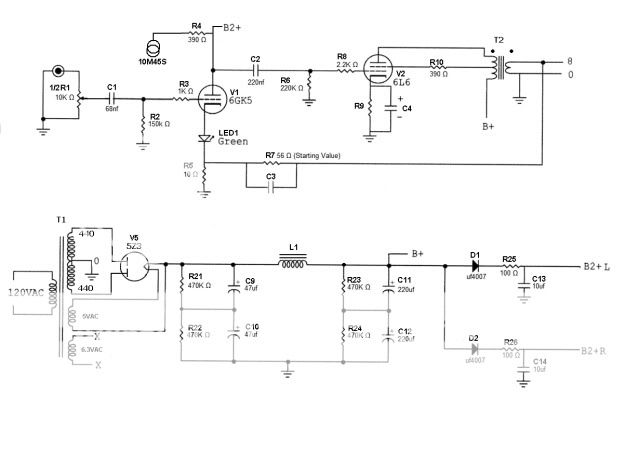
An interesting possibility is to replace R3 with a 10M45S constant current source (CCS). That tweak is good for linearity and makes sizing R23 and R24 very easy.
Eli - OK, I've pretty much gotten over the "keep it all analog" mindset. If I will be able to hear an improvement I'm all for it...What will the circuit change look like..and R23/24 values?
Thanks for you time and putting up with me
jt
Thanks for all the updates and info, I'll incorporate the changes and post my progress as time permits.
Eli - OK, I've pretty much gotten over the "keep it all analog" mindset. If I will be able to hear an improvement I'm all for it...What will the circuit change look like..and R23/24 values?
Thanks for you time and putting up with me
jt
The schematic symbol for a CCS is 2 interlocked circles. Refer to the attached "El Cheapo" schematic.
A 390 Ω RN65 seems good for the 10M45S current set part. Using the 10M45S CCS makes 100 Ω fine for R23 and R24. The exact voltage B2+ comes in at is no longer important. CCS loading makes things settle into place, automatically.
I previously stated that R4 should be 10 Ω. Making R6 56 Ω will feed back 15% of the net O/P voltage, which should be a reasonable starting point. If R6 is 100 Ω, 9% of the net voltage will be fed back.
Gimpy's remark about allowing WVDC headroom in PSU 'lytic selection makes sense. So, 350 WVDC parts will be used. Panasonic part # EEU-EE2V470 takes care of 47 μF. and Panasonic part # EET-HC2V221HA takes care of 220 μF.
Attachments
I was thinking about using some 6F5's in a future project. I agree with JT1 the the larger tubes are more entertaining to look at. Thanks Eli for steering us away from a bad choice, but the quest for a Octal high mu single triode remains. Any suggestions?
The 6F5 is not necessarily a bad choice, as long as you accept it for what it is. That's half a 'X7 in an Octal package. Isolate it from a load and you can gain a lot of Volts.
I liked the grid cap wiresI agree with JT1 the the larger tubes are more entertaining to look at...
So, I've spent enough time with this schematic that I think I can build it in my sleep...
Eli - As time permits can you review this and possibly fill im the remaining blanks...I'm about ready to start ordering parts and would like to get everything I can on hand. I know a few values are still unknown and some will be a fine tuning issue, but starting point values and ranges would be good and I can order everything at once.
Please take your time, and again I really appreciate your effort...
"The Eli Amp"
I like the 6f5 as the 6f5G not 6F5GT
its more sexier to look at.
anyways, if you end up not using the 6f5gt, I would suggest a 6SL7gt with the triodes in parallel like this one.
if you end up using the 6f5 I would go two, possibly three triodes in parallel to lower the tube's impedance characteristics
its more sexier to look at.
anyways, if you end up not using the 6f5gt, I would suggest a 6SL7gt with the triodes in parallel like this one.
if you end up using the 6f5 I would go two, possibly three triodes in parallel to lower the tube's impedance characteristics
Attachments
Last edited:
- Status
- This old topic is closed. If you want to reopen this topic, contact a moderator using the "Report Post" button.
- Home
- Amplifiers
- Tubes / Valves
- Help with 6F5/6L6 rebuild...