I know those psu are basically the same, just one is smaller.
the way you have those diodes zig zagged is wrong. they should be placed in the 4 outside spots. if chipamp.coms psu is labled different then audiosectors then just ignore the lables and do as is seen for audio sectors hook up.
i've done the same thing your doing with the ct on a 3886 kit. just do as seen in the diag. i posted.
Ok update,
I went ahead and switched the diodes and the jumpers to what it is on the pic included in this thread. My PSU is now working just fine! I got confused when using the same guide as LM3875. What I was doing was using the same "D" numbers as what is on the LM3875 PSU. That's why my diodes and jumpers were the way they were. Now I have to get the amp boards ready and wired up.") Thanks to impsick and AndrewT for the help. One other question. When measuring V+ and V- what readings should I be getting?
Thanks to impsick and AndrewT for the help. One other question. When measuring V+ and V- what readings should I be getting?
Cheers,
Chevy
I went ahead and switched the diodes and the jumpers to what it is on the pic included in this thread. My PSU is now working just fine! I got confused when using the same guide as LM3875. What I was doing was using the same "D" numbers as what is on the LM3875 PSU. That's why my diodes and jumpers were the way they were. Now I have to get the amp boards ready and wired up.
Thanks to impsick and AndrewT for the help. One other question. When measuring V+ and V- what readings should I be getting?Cheers,
Chevy
Alright another update.
I have completed all the wiring and installed the amp chips, but I'm having some issues. Before I connected the amp chips I switched on the PSU and the led lit up, so looks good. I then did a V+ to PG+ and V- to PG- with my multimeter and I get a beeping sound which I figure (because I didn't know for sure) was for connectivity. This happened on all 3 amps. I then connected the wires to the amp chip, mounted my heatsinks and connected the amp chips to them and then inserted the fuses and powered it up.
Then I went to take a reading with the multimeter to get the DC Offset by taking red from MMeter to red on the output terminal and black on the MMeter to black on the output terminal and then set MMeter to DCV and my small setting being 200m and I got nothing. No reading, just .000. I'm really not sure what's wrong. So I then hooked it up to my preamp and some crap speakers I have kickin' around. Only one channel works, but yet they are all assembled the same. Am I measuring DC offset correct? What might be some possible issues? I know that 2 off the amps work because I used them in a 2 channel amp that I built last year at this time. The only difference is I have added a xformer and PSU for each channel.
If the PSU LED lites up does that indicate that the PSU is working correctly?
Help!!
Chevy
Measure the supply voltages AT the supply end.
Sorry I don't understand. Supply voltage..... supply end??
Measure the mains voltage going into the transformer
From the mains coming in from the back of the amp I get 118Vac. I get 118Vac right through to the switch and then to the fuses. Then from the fuse into the Xformer.
I then measure AC1 and AC2 on the PSU and I get 30.3Vac. As I was doing this the chips seem to be getting a little hot to the touch. I turned off the amp right away. It wasn't as I was testing, but in general they seem to be getting hot. You could sort of smell the heat.
Measure the supply voltages at each amp.
Sorry I don't don't know what I'm measuring, V+, V-, PG+ and PG-?
Thanks,
Chevy
yeah something is wrong. your using a ct power supply right? Double check that you got all that and the proper jumpers set up right.
its really easy to miss a detail especially in that area.
Make sure to got V+ and V- going to the right spots on the amp boards.
and last but not least are your chips insulated? Black coating all around it even on the back where your heat sink would be touching?
its really easy to miss a detail especially in that area.
Make sure to got V+ and V- going to the right spots on the amp boards.
and last but not least are your chips insulated? Black coating all around it even on the back where your heat sink would be touching?
yeah something is wrong. your using a ct power supply right?
Yes, I'm using a CT xformer. The 2 outside wires connected to AC1 and AC2. The black wire connected to PG+.
Make sure to got V+ and V- going to the right spots on the amp boards.
I have triple checked to make sure all wires from the PSU board are going to the right connections on the amp board. I did find that I had a couple of poorly soldered wires that I have replaced.
last but not least are your chips insulated? Black coating all around it even on the back where your heat sink would be touching?
Yes, chips are insulated. The kit was bought from Brian GT.
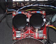
Here is a pic of the PSU board. I'm wondering if the jumpers are maybe wrong.
Thanks,
Chevy
Attachments
Just two black insulated jumpers fitted?
Come on folks, that does not look like previous postings.
Remember post 50?
I think you will find just a volt or two at the amplifier board.
Come on folks, that does not look like previous postings.
Remember post 50?
But you will only be able to do this if you have the light bulb fitted.Measure the supply voltages at each amp.
I think you will find just a volt or two at the amplifier board.
Just two black insulated jumpers fitted?
There is actually 3 jumpers. You can't really see the third. It's right below the second long one.
think you will find just a volt or two at the amplifier board.
Would that be DC volts or AC volts? I would assume DC, but I thought I would ask anyway.
D4 and D7 should be jumpered not D2 and D5.
I'm really getting confused here. D1, D4, D5 and D8 all have diodes. One on each corner, like I was told. If you refer to post 40 in this thread, I quote:
That is what I did. So if I need to jump D4 and D7 how can I do that with a diode in D4? The only spots left to jump are D2, D3, D6 and D7.you should have 4 diodes all on the outside. take those diodes in the middle and put then on the outside spots. the middle there is where you should have those jumpers
Does anyone have a pic they can post of an LM3886 PSU using a CT Xformer? Where are the diodes and where the jumpers go?
Chevy
i know there is 3
you have the one that you cant see in the wrong spot!
it should be in the spot above.
c'mon man look at the diagram carefully.
here it is upside down. does it make sense now where you messed up?

just move D2 and D5 up one spot to D4 & D7
that is the remaining holes on D4 & D7
you have the one that you cant see in the wrong spot!
it should be in the spot above.
c'mon man look at the diagram carefully.
here it is upside down. does it make sense now where you messed up?
just move D2 and D5 up one spot to D4 & D7
that is the remaining holes on D4 & D7
- Status
- This old topic is closed. If you want to reopen this topic, contact a moderator using the "Report Post" button.
- Home
- Amplifiers
- Chip Amps
- Help wiring power to 3 channel amp with one plug