The PSU uses a center tapped transformer and since I have on my transformer 2x30V rails I need to connect the right wires together and I rather ask before doing it wrong ") The PSU is for the D1 I/V stage.
The PSU is for the D1 I/V stage.
The transformer has wires:
sec1 = black, white (sw/ws)
sec2 = red, yellow (rt/ge in german)
To reduce the number of combinations, white, red and yellow are the wires we can build pairs with, black is out.
For a center tap I could then connect:
white and red
or white and yellow
What worries me are the phases of the secondary windings.
Browsing the web I found some transformers having a dot indicating the relative phase of the secondary to the primary winding. My transformer doesn't have a dot.
And for a center tap transformer I've found here that one sec. winding is in phase and one is 180 out of phase.
For one in phase: black and white
and 180 out of phase: white I connect with the last one, which is yellow. this is the center tap, and red is then -V.
Here's also a useful link on phases.
Phasing : Transformers - Electronics Textbook
What happens if I get it wrong? Can I try both combinations and measure the phases on an oscilloscope?
Thanks,
Martin
The PSU is for the D1 I/V stage.The transformer has wires:
sec1 = black, white (sw/ws)
sec2 = red, yellow (rt/ge in german)
To reduce the number of combinations, white, red and yellow are the wires we can build pairs with, black is out.
For a center tap I could then connect:
white and red
or white and yellow
What worries me are the phases of the secondary windings.
Browsing the web I found some transformers having a dot indicating the relative phase of the secondary to the primary winding. My transformer doesn't have a dot.
And for a center tap transformer I've found here that one sec. winding is in phase and one is 180 out of phase.
For one in phase: black and white
and 180 out of phase: white I connect with the last one, which is yellow. this is the center tap, and red is then -V.
Here's also a useful link on phases.
Phasing : Transformers - Electronics Textbook
What happens if I get it wrong? Can I try both combinations and measure the phases on an oscilloscope?
Thanks,
Martin
Attachments
Try connecting white and red together to form the center tap. After connecting AC to the primary, measure the voltage between Black-white and the voltage between red-yellow and then the voltage between black-yellow. If the secondary windings are "in phase" then the last measurement will be the sum of the first two. If "out of phase" then the last measurement will be near zero Volt.
Great, in phase double voltage, 180 out of phase 0 V ... makes sense
Try connecting white and red together to form the center tap. After connecting AC to the primary, measure the voltage between Black-white and the voltage between red-yellow and then the voltage between black-yellow. If the secondary windings are "in phase" then the last measurement will be the sum of the first two. If "out of phase" then the last measurement will be near zero Volt.
Will systematically test the PSU during the build. To mains I won't connect anything without a 4 A mid-speed fuse and before double-checking. Thanks for the Mains bulb tester suggestion
Before you connect any untested equipment to the mains, build your self a Mains Bulb Tester.
Feeding mains power in through the tester allows one to power up safely and not risk blowing up equipment that is wired incorrectly.
Yes, always use a lamp limiter when first testing mains powered equipment.
Incidentally, there are rumours that the EU is thinking of banning halogen bulbs from next year so we may all have to stock up soon. I don't know if cheap "rough usage" bulbs from the east will continue to be available in pound shops.
Incidentally, there are rumours that the EU is thinking of banning halogen bulbs from next year so we may all have to stock up soon. I don't know if cheap "rough usage" bulbs from the east will continue to be available in pound shops.
When you buy a transformer off a reputable dealer they usually come with an instruction sheet. This will give the colours of the wires and what phase the yare in.
If a instruction sheet didn't come with the transformer then look on their website for one.
I connected a transformer up once and blew out the mains fuse and my house circuit breaker ! So I have to be plus one on using a mains bulb in series with the primary.
If a instruction sheet didn't come with the transformer then look on their website for one.
I connected a transformer up once and blew out the mains fuse and my house circuit breaker ! So I have to be plus one on using a mains bulb in series with the primary.
Try connecting white and red together to form the center tap. After connecting AC to the primary, measure the voltage between Black-white and the voltage between red-yellow and then the voltage between black-yellow. If the secondary windings are "in phase" then the last measurement will be the sum of the first two. If "out of phase" then the last measurement will be near zero Volt.
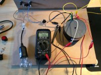
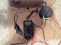
finally found time to test it with fuses and bulb tester in place and ...
bulb flashes only briefly when I connect to mains, this is good
the measurements are ???
the sec1 and sec2 measured are 32V, which is expected
for center tap
A: after connecting white and red and measuring between black and yellow my multimeter fluctuates between 0 and ~35V.
B: when white and yellow are connected, measuring between black and red shows 0V, which is also fine for out of phase
does anyone know why I get the fluctuation in A and not steady ~65V for in phase secondaries?
I've already written to the company I bought the transformer from, might take some time before they reply.
No worries, I am not plugging anything in before I know what is going on
, but I'd really like to know . Made a photo of the setup, couldn't catch the changing measurements, but they do fluctuate.Thanks!
Attachments
Last edited:
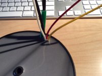
you have 6 wires coming out og the transformer.
You have two of these connected to the mains.
That leaves 4 secondary tappings.
These are likely to be two separate windings of a dual secondary transformer.
Did you measure the windings and label them before you connected to the mains?
You have two of these connected to the mains.
That leaves 4 secondary tappings.
These are likely to be two separate windings of a dual secondary transformer.
Did you measure the windings and label them before you connected to the mains?
you have 6 wires coming out og the transformer.
You have two of these connected to the mains.
That leaves 4 secondary tappings.
These are likely to be two separate windings of a dual secondary transformer.
Did you measure the windings and label them before you connected to the mains?
Hi Andrew,
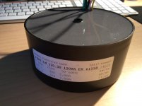
the transformer has a sticker (in the first post) showing:
primary = two black wires (which are also different thickness then the secondaries)
sec1 = black, white (sw/ws)
sec2 = red, yellow (rt/ge in german)
it's a 2x 30V and 2A transformer rated 120VA
I've measured the resistances just in case.
for stepping down from 240V to 30V, the resistance should be lower on the secondary side and they are.
black/black primary: resistance 17.7 ohm
for sec1 black/white: 2.4 ohm
for sec2 red/yellow: 2.4 ohm
black to red or yellow: infinite
white to red or yellow: infinite
I read somewhere transformers have a much more complicated wiring inside than the simplified schematic one works with N1/V1 = N2/V2
so now I've measured also for wiring A:
for wiring in A: resistance black-yellow is 3.8 ohm
between black and red : 3.1 ohm (intstead expected 2.4) so there is some internal resistance there ???
I am very much in the dark
Martin
Sorry if this sounds obvious but you have the tranny in front of you... we don't
I can't help but notice your meter is showing a mv symbol on its display in the picture. So have to ask The enamelled wire will be varnished. Make sure you scrape it off to get a good connection. Its not always obvious and it will give very misleading results if the contact is poor.
I can't help but notice your meter is showing a mv symbol on its display in the picture. So have to ask
The enamelled wire will be varnished. Make sure you scrape it off to get a good connection. Its not always obvious and it will give very misleading results if the contact is poor.Sorry if this sounds obvious but you have the tranny in front of you... we don't
I can't help but notice your meter is showing a mv symbol on its display in the picture. So have to ask
Thanks for the reply
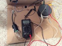
I wish I could teleport the transformer around, but until that happens you are stuck with me I'm afraid it's not much better than giving instructions to a blind monkey, and one shouldn't underestimate the monkeys. Well at least my hands are not shaking Sorry for the misleading photo, it was taken on my desk when the mains were out. The numbers range between 0V and 33V, in about 4 to 5s, displaying 0, sth blurry, 10V and 33.5V.
Wiggled the clamps up and down on the leads, and took different ones, measured continuity on the clamps... didn't find anything suspicious. I can also nicely measure 32V for sec1 and sec2.
Measured the mains with the voltmeter and noticed if the contact is bad it also shows fluctuations in the 4-5s interval.
Maybe it's really a bad contact somewhere.... going back to scraping the leads... fingers crossed
Attachments
Last edited:
Voltage fluctuations are to be expected on the mains, and will also be present on the secondary side. The fluctuations will be the same percentage as on the mains side. This would only result in a couple of V on the secondary at most. But in the picture (..._125.jpg) I see OL in the display. This means Over Limit. Since it seems to be in auto range, this would mean a voltage very much higher than the mains voltage. It seems unlikely that that could happen as even a € 10 - € 20 DMM will measure up to 250 VAC.
I would suspect the meter. Can you make sure this is working properly in the ACV range? Perhaps measure another transformer?
I would suspect the meter. Can you make sure this is working properly in the ACV range? Perhaps measure another transformer?
Last edited:
I find one of those little tiny grindstones on a hand held PCB drill works well. Good luck
scraping didn't help
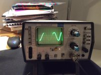
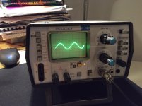
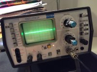
, but before using a bigger  and doing some soldering I've started measuring with my scope and the wiring scheme A (connected white to red and measure between black and yellow) seems to be in phase
 It's a super old scope, so the vertical scale is off, but wiring in A has twice the voltage (image 1) as measuring only one secondary (image 2). Just in case measured the wiring option B (where white and yellow are connected) and the voltage is 0 (image 3).
for some reason my multimeter is crap and measures one secondary and the mains fine, but has problems in the 60V range, which makes no sense
now I can move fwd to building the PSU
Thanks for all the help! I've learned a lot today
Attachments
Voltage fluctuations are to be expected on the mains, and will also be present on the secondary side. The fluctuations will be the same percentage as on the mains side. This would only result in a couple of V on the secondary at most. But in the picture (..._125.jpg) I see OL in the display. This means Over Limit. Since it seems to be in auto range, this would mean a voltage very much higher than the mains voltage. It seems unlikely that that could happen as even a € 10 - € 20 DMM will measure up to 250 VAC.
I would suspect the meter. Can you make sure this is working properly in the ACV range? Perhaps measure another transformer?
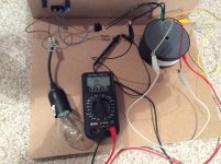
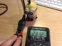
You are right Jitter, it is OL
and not 0. have to be more careful when looking at it.there is definitely sth odd with the multimeter, the max rating is 750V though. and the mains show ~230V in ACV mode (attached image), and also measuring one secondary shows 32V. I have no idea why it doesn't show the 60V properly. maybe there is an evil minion at work somewhere?
Martin
Attachments
A dual secondary has to be wired as a centre tapped to read the total voltage of the two windings.
Connect one tap (white) from X winding to one tap (yellow) from Y winding. You now have a three tap secondary winding.
Measure the voltage from white to black and from white to red. These should read as you had originally.
Now measure from black to red.
These can measure near zero volts or double the voltage readings you had before.
Do that and report back.
You are right Jitter, it is OL
there is definitely sth odd with the multimeter, the max rating is 750V though. and the mains show ~230V in ACV mode (attached image), and also measuring one secondary shows 32V. I have no idea why it doesn't show the 60V properly. maybe there is an evil minion at work somewhere?
Martin
Well, at least the scope showed that the winding scheme A works. And perhaps it's time to budget for a somewhat better multimeter, one without a minion inside...
Good luck with the build.
A dual secondary has to be wired as a centre tapped to read the total voltage of the two windings.
Connect one tap (white) from X winding to one tap (yellow) from Y winding. You now have a three tap secondary winding.
Measure the voltage from white to black and from white to red. These should read as you had originally.
Now measure from black to red.
These can measure near zero volts or double the voltage readings you had before.
Do that and report back.
Hi Andrew,
Thanks for your help. When white and yellow are connected I measured between black and red 0V.
connecting white and red and measuring between black and yellow my multimeter fluctuated (maybe it's faulty, although it measures the mains and one secondary winding fine), but the scope showed it's twice the voltage of one secondary winding. I guess this is fine.
Out of curiosity, could I also try the other possibility and connect black to either red or yellow and measure between white an the remaining/disconnected Y winding?
X winding: black/white
Y winding: red/yellow
- Status
- This old topic is closed. If you want to reopen this topic, contact a moderator using the "Report Post" button.
- Home
- Amplifiers
- Power Supplies
- help wiring multiple winding tranformer