This is a once in a lifetime project, and I would be very grateful for somebody's expertise. I had to replace capacitors in the original Kef crossover board but used a larger board because the larger replacements wouldn't fit. I have two problems: 1) I am unable to buy a schematic for the original Kef crossover board, and 2) I am unclear how to properly test the new board and avoid damaging my amp. Attached are photos of the original Kef board and a schematic I tried to make. Could some kind soul kindly mark up the errors in the schematic and advise me the sequence for testing the new board? Many thanks for any help.
Attachments
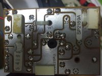
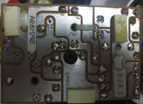
You need to flip the circuit board in a paint program to make sense of the wiring.
Then trace the earth and live input and the outputs.
The big 1000uF will be at the input to the bass for a start. I'd guess there is some sort of midrange filter and a second or third order tweeter filter on the Q driver.
Then trace the earth and live input and the outputs.
The big 1000uF will be at the input to the bass for a start. I'd guess there is some sort of midrange filter and a second or third order tweeter filter on the Q driver.
Attachments
Thats the crossover SP2189A for the Kef Q80 w. Passive radiator 33.8 liters.
The crossover for the Q60 is the ref. SP2181 for the reflex 19.8 liters.
Hi,
The crossover in post #1 is clearly labelled SP2189A.
rgds, sreten.
This is a once in a lifetime project, and I would be very grateful for somebody's expertise. I had to replace capacitors in the original Kef crossover board but used a larger board because the larger replacements wouldn't fit. I have two problems: 1) I am unable to buy a schematic for the original Kef crossover board, and 2) I am unclear how to properly test the new board and avoid damaging my amp. Attached are photos of the original Kef board and a schematic I tried to make. Could some kind soul kindly mark up the errors in the schematic and advise me the sequence for testing the new board? Many thanks for any help.
Send KEF an email explaining your situation / requirements and they will help.
I needed T/S details of a KEF drive unit.... I got their phone number from their website and phoned them up, 3 days later they sent me an email with the details attached and an open invite to tour the facilities.
The SP2189 is the crossover of the KEFkit60 as well and is fully documented:
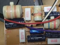
Hi, Dissi. You have been tremendous help and I hope to return the favour some day. First of all, you kindly showed that my attempt at drawing the schematic was total rubbish! Second, and most important, you clarified what I previously suspected, and probably explains why the prototype board doesn't work, that BENNIC incorrectly labelled R3 as 68 ohms. (Please see attached photo and correct me if I am wrong.) If I am correct, it may explain why BENNIC ignored the email clarification I sent them a couple of weeks ago. I don't wish to bother you again but hope you can help me if necessary. Best wishes, Ftpols
Attachments

Send KEF an email explaining your situation / requirements and they will help.
I needed T/S details of a KEF drive unit.... I got their phone number from their website and phoned them up, 3 days later they sent me an email with the details attached and an open invite to tour the facilities.
Cheers, Sippy. Many thanks for the suggestion. I believe Dissi may have solved my problem but would welcome your help if I get stuck again. Best regards, Ftpols
You need to flip the circuit board in a paint program to make sense of the wiring.
Then trace the earth and live input and the outputs.
The big 1000uF will be at the input to the bass for a start. I'd guess there is some sort of midrange filter and a second or third order tweeter filter on the Q driver.
Hi, Steve. Many thanks for all the advice you have been giving DiyAudioers and for my problem. I believe Dissi found the solution. BTW. I took my driving test in Portsmouth and survived many car crashes afterwards, which proves Portsmouth's driving tests are #1! Best regards, Ftpols
In the resistors, the R letter is the equivalent of the decimal dot. So 6R8 means 6.8 Ohm, R68 means 0.68 Ohm, and 68R means 68 Ohm.
Ralf
Hi, Ralf. A reply now from Italy, another great country. Many thanks for your feedback. I understand you are correct about how to read resistor ratings per the BS standard. But please compare the schematic very kindly provided by Dissi. You can see that R3 is rated as 0.68 ohms whereas BENNIC marked it 5WR68J, which I understand means 5W 68 ohms 5% tolerance. By comparison, BENNIC marked R1 as 5W3R3J, which I understand means 5W 3.3 ohms 5% tolerance. Either I am nuts or BENNIC and KEF don't use ISO-certified quality manuals. Best regards, Ftpols
Last edited:
Hi, Ralf. A reply now from Italy, another great country. Many thanks for your feedback. I understand you are correct about how to read resistor ratings per the BS standard. But please compare the schematic very kindly provided by Dissi. You can see that R3 is rated as 0.68 ohms whereas BENNIC marked it 5WR68J, which I understand means 5W 68 ohms 5% tolerance. By comparison, BENNIC marked R1 as 5W3R3J, which I understand means 5W 3.3 ohms 5% tolerance. Either I am nuts or BENNIC and KEF don't use ISO-certified quality manuals. Best regards, Ftpols
Ftpols hi,

Don't call BENNIC again. They think you are mad with them already.
R means, as giralfino already mentioned twice the decimal point so that copying from him R68 means 0.68 Ohm
Ok, let's see if I understand. That's a KIT and it comes with a crossover that might be used by both the projects Kit-60 and Kit-80 probably?! Thanks.The SP2189 is the crossover of the KEFkit60 as well and is fully documented:
Ftpols hi again,
Can you explain the forum, if you don't mind and if you know, why you have a crossover
(considered by the literature) to belong to another speaker i.e., Q60 speaker vs. Q80 crossover.
Ok, let's see if I understand. That's a KIT and it comes with a crossover
that might be used by both the projects Kit-60 and Kit-80 probably?! Thanks.
Hi,
The Kef Q60 and Kefkit Q60 pages don't agree
on the x/o's types used for the Q60 and Q80.
One of them is clearly wrong, seems the Kef page.
Explore KEF - KEFkit 60, 80, 90 - KEF United Kingdom
Explore KEF - Q60, Q80, Q90 - KEF International
rgds, sreten.
Last edited:
Please re-read what I wrote, and look at where the R is.
5WR68J means a 5W 0.68 Ohm 5% tolerance resistor (not a 68 Ohm resistor, which should be a 5W68RJ), so the Bennic marking is correct.
Ralf
Hi, Giralfino. Your explanation was very clear. Many thanks for correcting me. Best regards, Ftpols
Ftpols hi again,
Can you explain the forum, if you don't mind and if you know, why you have a crossover (considered by the literature) to belong to another speaker i.e., Q60 speaker vs. Q80 crossover.
Hi, Inductor. I bought the Q60's new in 93/94. They have never been repaired or modified. HF driver is SP1276, LF driver is SP1280, Crossover board is SP2189A. I believe later production used a SP1353 HF driver. Best regards, Ftpols
Many thanks.Hi, Inductor. I bought the Q60's new in 93/94. They have never been repaired or modified. HF driver is SP1276, LF driver is SP1280, Crossover board is SP2189A. I believe later production used a SP1353 HF driver. Best regards, Ftpols
Help wanted with Kef Q60 (SP2189A) crossover testing
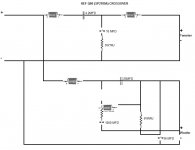
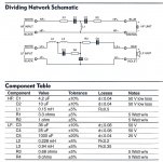
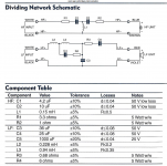
Gents, Attached is the circuit diagram kindly provided by Dissi. All the caps are bipolar. HF Circuit: I can do a continuity test with a multimeter from HF+ input to C1 and from C2 to driver HF+. I can't test continuity through C1 and C2. (Same applies to original KEF board and parts.) LF circuit: Same situation. I simply want to test each circuit from end to end before soldering the crossover to the drivers and input terminals and doing some damage. Many thanks for your expertise. Ftpols.
Many thanks.
Gents, Attached is the circuit diagram kindly provided by Dissi. All the caps are bipolar. HF Circuit: I can do a continuity test with a multimeter from HF+ input to C1 and from C2 to driver HF+. I can't test continuity through C1 and C2. (Same applies to original KEF board and parts.) LF circuit: Same situation. I simply want to test each circuit from end to end before soldering the crossover to the drivers and input terminals and doing some damage. Many thanks for your expertise. Ftpols.
Attachments
- Status
- This old topic is closed. If you want to reopen this topic, contact a moderator using the "Report Post" button.
- Home
- Loudspeakers
- Multi-Way
- Help wanted with Kef Q60 (SP2189A) crossover