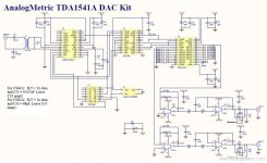
Hi,
I have just built the analogmetric tda1541a dac kit...but I am not sure what type of clocking it uses, ie re-clocking, synchronous, etc.I would like to add a discrete clock as I have a surplus lc audio clock 2 (45mhz ) and was going to change the crystal on it to 11.296mhz.
I have just built the analogmetric tda1541a dac kit...but I am not sure what type of clocking it uses, ie re-clocking, synchronous, etc.I would like to add a discrete clock as I have a surplus lc audio clock 2 (45mhz ) and was going to change the crystal on it to 11.296mhz.
Attachments
sounds good
Hi Hotiron,
It sounds very good...but it is very sensitive to component changes such as retifier diodes and main resevoir caps. I am using mine with a fet output buffer stage, bf245a/bs170..I felt it sounds better than all the op amps I tried..ad711 was the best of them.I also tried several caps for ic decoupling..oscon, Nichicon muse, panasonic fm,blackgate standard and rubycon za..the only one I didnt like was the Rubycon za, much to stark for my liking...probably the two best I liked were the pana fm and blackgate.
I have also built the AMB dac with wolfson chip very nice too..altho in a hi end system the tda1541 would be superior.
I am using a modified sb3 as source...tho I still feel it is holding back a bit.
When it comes to clocking ..dem clocking..re clocking....etc I am a bit lost...maybe one of the clock guru's will try and explain the differences to me..
hope this helps.
You don know what are those resistors are for... but you are saying that "altho in a hi end system the tda1541 would be superior".
That's a good demonstration of how urban legends are perpetuated by people with limited (that means just "some") knowledge in the digital field.
That's a good demonstration of how urban legends are perpetuated by people with limited (that means just "some") knowledge in the digital field.
some people
SoNic_real_one...there are hundreds of different ways that a tda1541 dac can sound, some of which I have described earlier...obviously you are not smart enough to absorb that information. the tda1541 dac can sound good or bad, depending on how it is implemented. Just because I dont know what the lpf resistors are for ( low pass frequency as a guess ) dosn't mean the dac will sound good or bad... and as it states on the schematic they are optional.
Have you heard both dacs??if so, in what configuration???
So if you can't add constructive criticism...then go ahead and be a ******.
I2S has a bit clock. So the data is clocked in on that, and samples are presented on the WS signal.
A 'clock' as you put it in the normal sense usually refers to the master clock, which runs at something like 11 or 16 MHz. You need this to drive the decoder or digital filter, but not this DAC.
The resistors are used to reduce the current going into the DAC to reduce distortion. A LPF is apparently better still (I haven't tried). If you search for a thread called 'tda1541 info', you'll find a lot of info on that there.
Reclocking can be used to square up the I2S lines, basically using a bank of flip flops and a master clock to clock the data into the flip flops. The idea is to reduce jitter induced by previous stages by reclocking to a low jitter clock.
DEM reclocking: The TDA1541A uses Dynamic Element Matching (DEM) which uses an oscillator to switch between different internal current sources. DEM reclocking replaces the oscillator signal with one derived from an assumed better clock. Again more in that thread on this.
not working
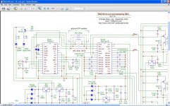
I removed the 74hc4040 chip and cyrstal ( schematic is on the first post here ) from the board and then operated as per philpoole's schematic...but no sound at all...but ok when I went back to my original setup.
I checked all connections from cs8414 to tda1541 dac and all seemed ok...does it matter that the reciever is not cs8412 as in philpoole's shematic ?
any tips what I should look for?.
That wasn't my schematic!
I don't know the cs841x, but maybe you need to change a voltage on a setup pin to specify a different output mode or something?
More importantly, why did you see the need to remove it?
I think for a NOS DAC, you be better off improving power supplies, or something like that to start with.
I don't know the cs841x, but maybe you need to change a voltage on a setup pin to specify a different output mode or something?
More importantly, why did you see the need to remove it?
I think for a NOS DAC, you be better off improving power supplies, or something like that to start with.
No, there are not for "reducing the current". It's on digital side, current it is only ON or OFF. There are there for reducing the front of the signal. Signals with fast fronts can put out ridiculous edge rates which can cause EMI and couple to other traces, they can stress your power supply, they can cause ringing on traces that can make chips do weird things, you name it. Especially if are long traces and if there are going to a slower device (like the old TDA 1541).philpoole said:The resistors are used to reduce the current going into the DAC to reduce distortion. A LPF is apparently better still (I haven't tried).
Thanks for the correction. However, from what I recall from the TDA1541 info thread (link below), a Philips engineer from the time mentioned this and its affect on the chip's substrate, and how also the voltage levels could be adjusted to improve matters, as well as an actual LPF.
I admit I haven't investigated this in detail, but simply refer to this thread - that's why I used the word 'apparently' for some of this.
I do also agree with your statements in the general sense, but I get the impression there is a special case here.
(Don't shoot the messenger)
http://www.diyaudio.com/forums/show...erpage=25&highlight=tda1541+info&pagenumber=1
I see that there is the same opinion: "Not faster than 10 to 30nsec rise time. This rise time is already faster than required is the ft of the pnp is taken in acount. A lateral pnp is in this process not faster than 10MHz, a vertical pnp slightly faster."
The current in itself I don't think it is a problem, the chip is calculated for the TTL signals after all. But the ultra fast rise time it is what it was not taken into account at the time when this DAC was designed. CS has nice fronts for the modern circuits and for 96kHz Fs, but for this particular case it is different.
The current in itself I don't think it is a problem, the chip is calculated for the TTL signals after all. But the ultra fast rise time it is what it was not taken into account at the time when this DAC was designed. CS has nice fronts for the modern circuits and for 96kHz Fs, but for this particular case it is different.
good
Sorry....I should have said as supplied by philpoole.That wasn't my schematic!
okI don't know the cs841x, but maybe you need to change a voltage on a setup pin to specify a different output mode or something?
Thanks for the tipI think for a NOS DAC, you be better off improving power supplies, or something like that to start with.
ooops
Bugger! ( another mistake )...hotiron supplied the schematic.....sorry bout that philpoole !But I didn't post the schematic either!
Re: not working
if you want try your dac without reclocking (HC4040 and XO removed) you have to change the 8414 from mode 3 (M0=1, M1=1, M2=0, M3=0) to mode 2 (M0=0, M1=1, M2=0, M3=0).
In mode 3 FSYNC and SCK are input (generated from XO and HC4040), in mode 2 are output generated internally with the clock recoverd via pll from spdif input.
As always it's all in the datasheet.
Ciao
Andrea
Chilli6565 said:I removed the 74hc4040 chip and cyrstal ( schematic is on the first post here ) from the board and then operated as per philpoole's schematic...but no sound at all...but ok when I went back to my original setup.
I checked all connections from cs8414 to tda1541 dac and all seemed ok...does it matter that the reciever is not cs8412 as in philpoole's shematic ?
any tips what I should look for?.
if you want try your dac without reclocking (HC4040 and XO removed) you have to change the 8414 from mode 3 (M0=1, M1=1, M2=0, M3=0) to mode 2 (M0=0, M1=1, M2=0, M3=0).
In mode 3 FSYNC and SCK are input (generated from XO and HC4040), in mode 2 are output generated internally with the clock recoverd via pll from spdif input.
As always it's all in the datasheet.
Ciao
Andrea


- Status
- This old topic is closed. If you want to reopen this topic, contact a moderator using the "Report Post" button.
- Home
- Source & Line
- Digital Line Level
- help understanding different clocking for tda1541