It won't work properly without it because the feedback point is not sampling the output terminal. And if you move the feedback connection over to the output terminal then you would not need two separate 220 ohm resistors, a single resistor would be fitted.
Do some continuity checks and see where the feedback resistor goes.
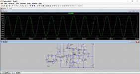
still going to Q2 R6 as feedback
The gain looks to high as well.
from your picture i see your value at R8 is 10ohm and R9 is 4K
the original is 180ohm and 12K
so are they the suspect of negative rail peak is under positive rail peak???
R8 needed to be lowered to keep the output stage bias reasonable. R9 at 4k gives around 6ma in the VAS (voltage amplifier stage) which is a typical workable value.
We are just working with a simulation here. Its fine as far as it goes, but is it really how your amp is configured ? That's the big question")
R9 should ideally be 'bootstrapped' as well. That would help with the negative peaks.
We are just working with a simulation here. Its fine as far as it goes, but is it really how your amp is configured ? That's the big question
R9 should ideally be 'bootstrapped' as well. That would help with the negative peaks.
R8 needed to be lowered to keep the output stage bias reasonable. R9 at 4k gives around 6ma in the VAS (voltage amplifier stage) which is a typical workable value.
We are just working with a simulation here. Its fine as far as it goes, but is it really how your amp is configured ? That's the big question
R9 should ideally be 'bootstrapped' as well. That would help with the negative peaks.
it works well too here
lowering R8 and VAS is ok...
this amplifier, your question, the configuration??? if you ask it, me too
cause this one is not mine
but the last thing i will ask for you
can i changed those final transistor into TIP41C and TIP42C???
cause no one sell original transistors here
also can i change all driver transistor into C945 and a733???
Last edited:
Like this.
yeah...
this one works well here!!!
and it solving my problem...
TIP41/42C should be OK.
The 2SC945 is a bit underrated for a driver 0.25w, 150 milliamp. I wouldn't use those.
alright boss...
i will do it!!!
but what is your suggestion for other???(not A733 and C945)
cause today i have been driving around my town for 4 hours only for finding C2073 and A940 but no one sell them(not including traffic jam, crowded, some police DUI check etc)
The mpsa06/56 pairs will work and are pretty common. Why high voltage low gain types were chosen to be installed is another mystery.
thanks dude
i will try it
high voltage low gain???
not only you ask it, me too
you know, made in china sometimes make us crazy
Are we all sorted then
lol
i don't understand what you said
but you are very great man
thank you very much for your help
i am so happy right now...
Hi fandi,
...I may just be echoing what others had previously stated. You have been fixing the amp in simulation but before trying all the changes in the actual pcb it is always a good idea to unsolder one leg of all the resistors and diodes and see if the actual component in place corresponds with the value indicated on the board. China made boards always had them printed on top of the board. They always place components symmetrically but beware of connecting jumper wires, make sure that there are no missing wires
If the amp has been repaired before make sure that it was not messed up because the output devices in the picture looks suspicious, I can only recommend at this rate of power level, TIP41c/42c will work just fine. Most low power China amps uses them.
Regards,
Albert
Hi fandi,
...I may just be echoing what others had previously stated. You have been fixing the amp in simulation but before trying all the changes in the actual pcb it is always a good idea to unsolder one leg of all the resistors and diodes and see if the actual component in place corresponds with the value indicated on the board. China made boards always had them printed on top of the board. They always place components symmetrically but beware of connecting jumper wires, make sure that there are no missing wires
If the amp has been repaired before make sure that it was not messed up because the output devices in the picture looks suspicious, I can only recommend at this rate of power level, TIP41c/42c will work just fine. Most low power China amps uses them.
Regards,
Albert
good advice man...
connecting jumper wires is an issue for me cause they use small jumper wires for handling big voltage and big current
this amplifier was repaired once for only changing final transistor(my relatives said but i am still can't trust her
)you are right boss!!!
most China amplifier using TIP41C/TIP42C as their final transistor...
this pairs always i have found when fixing low cheap active speaker with brand said "MADE IN CHINA"...
thanks bro
i will use your words for completing my job
Good luck
I am following your schematic that you change R8 into 10 ohms and put another caps after R9...
IT WAS ALMOST DISASTER FOR ME...
When i turning on power button, i have just heard BIG BIG BUG HUM and suddenly i turn off it
Touching those TIP42C...
THEY ARE SO HOT...
Now, i have no idea...
But i will try my version...
Only change R9 to 1K...
My wish, GOD bless me...
The reason is because the bias current is to high and the amplifier has no manual adjustment.
You can short out one of the diodes and try again with a 10 ohm If its OK then increase the 10 ohm until you get the required bias. It really needs a proper Vbe multiplier fitting in place of those diodes.
You can short out one of the diodes and try again with a 10 ohm If its OK then increase the 10 ohm until you get the required bias. It really needs a proper Vbe multiplier fitting in place of those diodes.
This is what I said earlier
Reducing the value of R9 will tend to increase the output stage bias. As its not adjustable then that is probably not a good thing.
The reason is because the bias current is to high and the amplifier has no manual adjustment.
You can short out one of the diodes and try again with a 10 ohm If its OK then increase the 10 ohm until you get the required bias. It really needs a proper Vbe multiplier fitting in place of those diodes.
I am give up...
Sorry i can not do it like what you said before...
I am so sorry...
I have plan for use their origin value of passive components
But i have small plan like my 2N3055/MJE2955
I put a resistor after Q5 to Q6...
It was 150 ohm...
But one question
Is R7 33K contributing give hum
- Status
- This old topic is closed. If you want to reopen this topic, contact a moderator using the "Report Post" button.
- Home
- Amplifiers
- Solid State
- help this mikawa amplifier, cheap but weird