I can attest to the bad power causing transformer hum. Every time my wife turns on her hair dryer, the 1000VA trafo in my big amp starts to hum. The hum dies down after a few seconds, but it is unmistakeable, I can clearly hear her hair dryer through the floor above my listening room.
JJ
JJ
Nelson Pass said:maybe someone here will share an example.
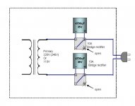
Attached simplified sketch shows my example of the dc-filter as
I’m using.
We see only about maximum 0.66V across the polarised
electrolytic cap. This means that the cap sees reverse voltage
of about maximum 0.66V. This figure is, however, too small
for us to consider it as any cause of trouble in the cap.
In general, if I see the fuse sizes of the power amps, they
are less than 10A. So, the 10A bridge rectifier is deemed
big enough for us to apply on the primary side.
It works well.
Good luck!

Attachments
Looks to me as though any DC greater than the diode drop is going to go straight through. The cap won't block anything because the DC (assuming it's greater than about .6V or so) will bypass the cap via the bridge. Actually, I don't see that the caps are doing much of anything, but perhaps I'm missing something.
The fuse rating, particularly if it's a SLO-BLO, doesn't count for much in sizing a bridge rectifier. What could potentially kill the bridge is the current surge at turn-on. Most diodes are able to take momentary currents much higher than their rated current, and the inrush depends on what's on the other side of the transformer, so hopefully between those two everything is okay in the current department.
Grey
transformer hum
I have a 1000 va Plitron in my Aleph 4 that hums. It is all mechanical. Plitron told my it was caused by DC in my house supply, and gave me no recourse to swap it out. I installed an isolation transformer and it reduced, but did not eliminate the hum. Of course now the isolation transformer hums as well. I plan to carefully inject some kind of glue or varnish into the area where the windings are humming. If I could unwrap the fiberglass tape surrounding the outside windings I would just dip it into some kind of sealant, but the epoxy plug in the middle makes it impossible to unwrap the tape. I may move the isolation transformer and put a sound absorber around it, or try a DC trap. If anyone has any advice in regards to quieting the loose windings, I would be grateful for their input. The transformer was expensive and I am really disappointed in the noise.
Don
GRollins said:Looks to me as though any DC greater than the diode drop is going to go straight through. The cap won't block anything because the DC (assuming it's greater than about .6V or so) will bypass the cap via the bridge.
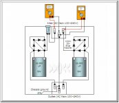
No, Babowana's circuit would be the correct one. The cap/diode
pair is back-to-back. I do think 35A rectifiers are a good idea,
any maybe higher voltage / current capacitors.
Remember folks, these are high voltage AC line circuits.

This often does the job, but not always. The other way to
improve upon it is to put a resonant parallel LC network across
the AC line, with the resonance tuned to the line frequency. I
believe this is what the Richard Grey products are doing, and
they seem to work well.

Whoops - just noticed the bridge wire on the rectifiers. It will
still work - the drop will net at 1.2 volts, though, not .6. For
twice that much, connect the AC lines through the ~ and bridge
the + to - on each rectifier.
Or leave the bridge wire off altogether.
Hi,
Would it be possible to use Babowana's filter as a generic one, i.e., in series with not just one transformer, but more devices.
More specifically, I have two amps, a preamp, an active crossover and a CD player connected to one mains splitter. Now, both amps have some hum and I thought that building a DC trap could be a good idea. But instead of opening both amps and doing two DC traps, I wanted to do just one, and put it between the mains wall plug and the splitter.
However, my CDP is using a SMPS psu, so I don't know if it matters or not...
I was planning to use 35 A bridges ans some 200v 220 uF caps (or they are too small?)
Regards,
Vix
Hi Vix,
I have used this more than 1.5years without no problem.
From time to time, I have sensed caps and found always cold
on operation. This covers my pre/power amps, tv, cd player,
tuner, dvd player.
The caps polarities to be as shown (i.e. back-to-back).
I have used this more than 1.5years without no problem.
From time to time, I have sensed caps and found always cold
on operation. This covers my pre/power amps, tv, cd player,
tuner, dvd player.
The caps polarities to be as shown (i.e. back-to-back).
Attachments
Babowana said:Hi Vix,
I have used this more than 1.5years without no problem.
From time to time, I have sensed caps and found always cold
on operation. This covers my pre/power amps, tv, cd player,
tuner, dvd player.
The caps polarities to be as shown (i.e. back-to-back).
This is exactly what I needed.
Thank You!
Hi,Vix said:Hi,
Would it be possible to use Babowana's filter as a generic one, i.e., in series with not just one transformer, but more devices.
More specifically, I have two amps, a preamp, an active crossover and a CD player connected to one mains splitter. Now, both amps have some hum and I thought that building a DC trap could be a good idea. But instead of opening both amps and doing two DC traps, I wanted to do just one, and put it between the mains wall plug and the splitter.
However, my CDP is using a SMPS psu, so I don't know if it matters or not...
I was planning to use 35 A bridges ans some 200v 220 uF caps (or they are too small?)
Regards,
Vix
a pair of 200uF caps in series are equivalent to 26.5ohms @ 60Hz.
If one wants to keep the diodes from passing (they don't block if they pass), then the voltage across the caps and diodes must be less than 600mVpk.
For that impedance and voltage the maximum current is about 23mApk.
The total load on the DC blocking circuit must be kept below that 23mApk value or the diodes will pass due to excessive voltage drop across the capacitors.
If the caps are increased to 2200uF then the maximum current is 250mApk. This will just about supply all the small current transformers in a small audio installation. I would not recommend that SMPS be fed through a DC blocker, I don't have a technical reason, just that the circuit is for eliminating transformer mechanical hum.
Putting 2 series connected diodes in inverse parallel, doubles the permissible voltage drop across the caps and is an easy way to double the current rating of the blocking capacitors.
A small power amp needs about 4700uF and double diodes and a large power amp 10mF to 22mF with double diodes for effective DC blocking.
High voltage caps are not required.
10V or 16V are acceptable, provided they are fitted back to back.
You might even get away with 5V or 6.3V caps but I wouldn't risk going that low.
BTW.
I hate the idea of putting opposite phases of the blocking into the Live AND the Neutral line.
Either fit both caps and diodes to the Live line or fit the whole circuit to the Neutral line.
Babowana said:
Attached simplified sketch shows my example of the dc-filter as
I’m using.
We see only about maximum 0.66V across the polarised
electrolytic cap. This means that the cap sees reverse voltage
of about maximum 0.66V. This figure is, however, too small
for us to consider it as any cause of trouble in the cap.
In general, if I see the fuse sizes of the power amps, they
are less than 10A. So, the 10A bridge rectifier is deemed
big enough for us to apply on the primary side.
It works well.
Good luck!
Thank you for the diagram. I ordered the parts from mouser to build this. I am going to put it into a small box so that its a bit like the commercially available devices so I also bought one of those IEC inlets with the filter on it for some added help. I'll have to see how it turns out but Im hoping for good results!
Well, Got this thing all built and it did quiet the buzzing transformer but thats not the real issue I was hoping to solve with it which unfortunatly I did not solve. I knew it was a long shot anyway but ah what the hell, Now I have something that at least does what its supposed to
Thought you guys would enjoy a couple pics. Thanks again for the schematic If I had to do it all over again I would have bought the 35 or 50A rectifiers instead of the 10A but this is only being used on my preamp anyway so its plenty. I also added a fuse for the heck of it and one of those filtering IEC plugs. The IEC is a 10A medical grade schuter and and put a 5A fuse in. Got the chassis at radioshack for something like 5 bucks too.
Thought you guys would enjoy a couple pics. Thanks again for the schematic
If I had to do it all over again I would have bought the 35 or 50A rectifiers instead of the 10A but this is only being used on my preamp anyway so its plenty. I also added a fuse for the heck of it and one of those filtering IEC plugs. The IEC is a 10A medical grade schuter and and put a 5A fuse in. Got the chassis at radioshack for something like 5 bucks too. An externally hosted image should be here but it was not working when we last tested it.
An externally hosted image should be here but it was not working when we last tested it.
An externally hosted image should be here but it was not working when we last tested it.
- Status
- This old topic is closed. If you want to reopen this topic, contact a moderator using the "Report Post" button.
- Home
- Amplifiers
- Pass Labs
- Help! Strong hum from transformer