Hello, I have a basic AB MOSFET amp that I built from an article some years ago. It has one 2SK134 / 2SJ49 output pair per amp, no parallel output FETs. It has worked well but recently the right channel blew. The output of this channel is now jammed to the negative voltage rail, about -37V. There is zero current through either output device (formerly approx 500mA when the amp was working).
I am assuming the problem is one of the output devices. Is that reasonable?
If so, to push the output voltage to the negative rail, is it more likely the 2SK134 (connected to the +ve rail) has failed, or the 2SJ49 (-ve rail)?
Are there any simple diagnostic measurements I can take, to locate the fault?
Many thanks
Attachments
I am assuming the problem is one of the output devices. Is that reasonable?
Yes..it is reasonable...i suspect one or both outputs are bourned.
Inspect also the source resistor , it can be also bourned.
Regards
Mosfets are fairly hardy devices, and not easy to damage under normal operating conditions (a short on a speaker line whilst running at high power could). If one or both of the output devices failed, more than likely it would have blown the rail fuses.
Check the voltages either side of the bias pot - if these are also at or near the negative rail, then problem is further forward of this.
Take a number of voltage readings and post the results referencing the schematic, and we may be able to help track it down.
Cheers
Check the voltages either side of the bias pot - if these are also at or near the negative rail, then problem is further forward of this.
Take a number of voltage readings and post the results referencing the schematic, and we may be able to help track it down.
Cheers
Also check the voltages on the VAS transistor and verify that it is saturated and that it is suppose to be, due to circuit function, [or nonfuntion](check the base & emitter voltages.)
If above is true, check the state of the differential transistors to verify that they are set to cause saturated VAS transistor, and then check the negative feedback loop to see if the "neg. input" transistor in diff. circuit reacts to the 'now -60V' output.
Someware in this loop you should be able to track down the mishap.
Unlikely, but one of the current source devices could have shorted.
overall, this is not a really complex circuit...you will figure it out")
If above is true, check the state of the differential transistors to verify that they are set to cause saturated VAS transistor, and then check the negative feedback loop to see if the "neg. input" transistor in diff. circuit reacts to the 'now -60V' output.
Someware in this loop you should be able to track down the mishap.
Unlikely, but one of the current source devices could have shorted.
overall, this is not a really complex circuit...you will figure it out
OK I have some measurements.
On the bad channel, -35V and -35V
On the bad channel, -34.7V and -34.7V
Base voltages on the differential inputs:
Good channel, 0V pos input, 0V neg input
Bad channel, -40.2V pos input, -39.5V neg input
Good channel, 0.74V and 10.5V
Bad channel, 0.0V and 0.0V
So, it seems the problem is not the output MOSFETs but some kind of short near the input? I checked the input RCA voltages: for the bad channel I measured -40.2V at both inputs (signal and shield).
I get the feeling I'm missing something blindingly obvious!?
On the good channel, +1.77V and -1.55VCentauri said:...Check the voltages either side of the bias pot - if these are also at or near the negative rail, then problem is further forward of this.
On the bad channel, -35V and -35V
On the good channel, +1.9V and -1.7Vjanneman said:Most probably the neg side device has failed, shorted. But then you should have SOME current through it. Measure the gate voltages of the mosfets, that should give you an initial pointer.
On the bad channel, -34.7V and -34.7V
Sorry, but I'm not sure which one is the VAScunningham said:...on the VAS transistor ...(check the base & emitter voltages.)
...check the state of the differential transistors to verify that they are set to cause saturated VAS transistor, and then check the negative feedback loop to see if the "neg. input" transistor in diff. circuit reacts to the 'now -60V' output.
Base voltages on the differential inputs:
Good channel, 0V pos input, 0V neg input
Bad channel, -40.2V pos input, -39.5V neg input
The CCS is set for 200uA. I checked the voltage drop across R12 (should be 0.66V) and R11 (should be 9.4V):-anatech said:I'd expect a high current flow if a FET had failed. I am looking at the current source(s) as a possible problem.
Good channel, 0.74V and 10.5V
Bad channel, 0.0V and 0.0V
So, it seems the problem is not the output MOSFETs but some kind of short near the input? I checked the input RCA voltages: for the bad channel I measured -40.2V at both inputs (signal and shield).
I get the feeling I'm missing something blindingly obvious!?
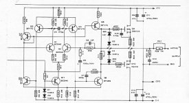
On the left portion of the schematic (on the previous page of the magazine article - and not shown in the attached scan) is a note saying "shield must be connected to 0V BEFORE applying power".
It would seem that this connection has come adrift.
If your main power supply earth is connected to chassis earth and mains power earth, then I would recommend connecting the input earths to main earth via 10 ohm 5W resistors anyway to avoid earth loops.
Cheers
Graeme
It would seem that this connection has come adrift.
If your main power supply earth is connected to chassis earth and mains power earth, then I would recommend connecting the input earths to main earth via 10 ohm 5W resistors anyway to avoid earth loops.
Cheers
Graeme
Solved!
Bingo! Rather sheepish and red-faced, I now remember how I built the amp all those years ago. I left the input of one channel unearthed, knowing that when I connect a preamp, both channels of the preamp will be earthed. I was very keen to avoid earth loops: perhaps too keen. It worked fine.
This explains why the amp "suddenly" developed a fault when I pulled it out for a look-over and to play with the bias settings, and fired it up with open inputs.
I have now added a link from the input earth/shield of this channel to the power supply ground, just like the 'working' channel has always had. I hope this doesn't cause any earth loop. I will find out this weekend.
Many thanks to all contributors on this thread. If anyone can explain 'why' it pulls the output to negative when the input ground is missing, I would appreciate the lesson.
Grant
anatech said:Looks like you are missing your input ground (top side R7). That would shut down your current sources and pull the output negative. This kills your bias as well.
-Chris
Bingo! Rather sheepish and red-faced, I now remember how I built the amp all those years ago. I left the input of one channel unearthed, knowing that when I connect a preamp, both channels of the preamp will be earthed. I was very keen to avoid earth loops: perhaps too keen. It worked fine.
This explains why the amp "suddenly" developed a fault when I pulled it out for a look-over and to play with the bias settings, and fired it up with open inputs.
I have now added a link from the input earth/shield of this channel to the power supply ground, just like the 'working' channel has always had. I hope this doesn't cause any earth loop. I will find out this weekend.
Many thanks to all contributors on this thread. If anyone can explain 'why' it pulls the output to negative when the input ground is missing, I would appreciate the lesson.
Grant
Hi Grant,
The leakage through C5 as your ground was pulled negative. Also consider that Q5 is a current source that is turned off. There may be a tiny amount of current flowing through Q8, and that is all it takes. I can't see the input side of the circuit, but Q1 may have been reverse biased leaving a trickle through Q2. Enough to create a slight leakage in Q4 and therefore Q8. Fancy explaination ... who knows?
I can't see the diagram clearly, I think Q8 is the BF459??
Glad you found it,
-Chris
anatech said:Make those 10 1/4W. You do not want to sustain a current flow.
-Chris
I usually make them higher power so they can withstand an earth fault in connected equipment without burning out, possibly resulting in DC speaker damage.
Cheers
Grounding
Hi Centauri,
Why not connect the speaker return, power supply common and input reference at a star ground? This would then connect to the earth ground through a resistance. By doing this you can still avoid a ground loop and not worry about a DC offset if that ground were to burn out. You would end up with a small hum as the chassis would no longer be referenced to the circuit ground. I can't see a differential between signal grounds L & R occurring. If it did you would have serious trouble!
-Chris
Yes, this is fine and is sometimes implemented in designs where the input earth is not isolated on the amp PCB - I have cured ground loop problems in old Phase Linear amps this way. Most Jands pro amps use both methods.
From a safety standpoint, the mains earth should be firmly connected to any input which connects to something people normally hold (microphones, musical instruments etc), and the power amp only really needs the mains earth as a reference.
Cheers
From a safety standpoint, the mains earth should be firmly connected to any input which connects to something people normally hold (microphones, musical instruments etc), and the power amp only really needs the mains earth as a reference.
Cheers
Hi Centauri,
Agreed as far as pro music amps go. This is a residential amplifier. The chassis is firmly grounded. I am recommending the internal circuitry be referenced to ground through the resistor. A similar situation exists with the preamp and other signal sources, except a turntable which is a floating source. The chassis of that is normally grounded as well. Therefore, we do not have the same situation the occurs in live sound. The desire is to eliminate ground loops. There should never be any substantial current flow in this situation.
The only exception would be a lightning strike nearby with a TV or VCR connected. All bets are off in those situations.
-Chris
anatech said:Hi Centauri,
Agreed as far as pro music amps go. This is a residential amplifier. The chassis is firmly grounded.
Most definately - any exposed metal chassis should be grounded, and grounded well. If the entire "signal" ground is isolated from chassis (via resistor), then management of ground loops is much easier. About the only situation I can think of where this may be a problem is in the event of insulation breakdown between primary and secondary of mains transformer, which would be very rare.
Cheers

- Status
- This old topic is closed. If you want to reopen this topic, contact a moderator using the "Report Post" button.
- Home
- Amplifiers
- Solid State
- Help requested: broken amp