Hi, I am trying to repair a friends Hafler XL280. One channel works fine, but the other is low in power and distorted. I have scratch built several amps but never repaired a MOSFET amp. Here is what I found:
- Power supply rails appear good at +- 64v and that voltage appears on output FETs both sides (drain)
- Power to the input stage from the single bridge for both channels appears to present +- 63.5vdc. That should be 75v?
- Fuses are OK and no parts look burned or damaged
- Output FETs on good side show 0vdc on case, but bad cannel shows votages varying from -1.4vdc to -2.3vdc on both n and p sources.
- Input to the output transistors with no signal is 0 on good side but varies from about -1.4 to over -2vdc on bad side on both the n and p gates.
I have downloaded the instruction and assembly manual, so I have the schematic, but there is very little troubleshooting information. The low voltage off the input stage bridge sure looks wrong, but I would think it would affect both channels equally, still the left channel sounds OK.
For checking other input board voltages, should I take the heatsinks off the chassis?
Any help would be hugely appreciated.
Marshall")
- Power supply rails appear good at +- 64v and that voltage appears on output FETs both sides (drain)
- Power to the input stage from the single bridge for both channels appears to present +- 63.5vdc. That should be 75v?
- Fuses are OK and no parts look burned or damaged
- Output FETs on good side show 0vdc on case, but bad cannel shows votages varying from -1.4vdc to -2.3vdc on both n and p sources.
- Input to the output transistors with no signal is 0 on good side but varies from about -1.4 to over -2vdc on bad side on both the n and p gates.
I have downloaded the instruction and assembly manual, so I have the schematic, but there is very little troubleshooting information. The low voltage off the input stage bridge sure looks wrong, but I would think it would affect both channels equally, still the left channel sounds OK.
For checking other input board voltages, should I take the heatsinks off the chassis?
Any help would be hugely appreciated.
Marshall
Thanks mrshow4u and anatech for such fast responses. Wow, this forum is great!
mrshow4u, the output fets do have gate resistors, I assume for load sharing. I've never heard the term gate stopper, but assume it is like the "grid stopper" for the tube gear where I have way more experience (started with dyna and heath before transistors were born!). I do have a scope and signal generator. I assume you are saying that I might see a good signal on the gate when I drive with say a 1k signal, but would not see one on the speaker output side. There is some signal coming through, but nowhere near what the other channel has. Could some but not all of the output fets be bad? I'm not sure I have equipment to test the fets.
anatech , The grid, oops I mean gate resistors are all OK, and there is no mass of wire melted together. By the way, after idling 10 minutes or so, the bad channel's heat sink was pretty cool, while the working channel's HS was just a little warm.
Can you tell me what you mean by checking continuity? Do I check for continuity between gate and drain? Should I be pulling the fets and checking continuity on each fet? I don't want to blow a fet that is good.
If any of the fets are bad, how do I get replacements? I understand they are very hard to get.
I'll dig out my scope and signal generator and load resistors and see what gives. Any hints would be appreciated.
Thanks a million guys!
Hi Truckee_Tango,
It sounds like your bias network is misadjusted or shorted.
Put your common meter probe on the output line. Measure to each gate line and tell us what you have for DC voltage.
The mosfet is a depletion mode device like a tube. If that resistor goes open, the gate floats high and the transistor conducts heavily, or oscillates. Either way, the transistor normally shorts.
-Chris
The "grid stopper" term is borrowed from tubes. Actually I think the signal should be at the gates, large but ugly. The feedback loop should be trying to compensate for the low output by making the signal much larger at the gates. I think the signal will be ugly at the gates because the loop basically sounds open at this point, and even open loop will not satisfy the inverting input. I think you might get something very "squarish" at the gates. Oh, that reminds me. Check for clampers across the gates. It might be something like a zener and a signal diode in series wired across the gates. I don't have the schematic, but some sort of voltage clamper. Just another thing to check.
mrshow4u There is a 1N4003 diode from what should be a higher voltage B+- to the front end to the lower 64 volts going to the output fets, but other than that no clamper that I see. The schematic is under the www.hafler.com site under tech support and archive tabs. I could send you the .pdf file, but it is a 4mb chunk. I have not checked those diodes, but it is suspicious that I don't see the 75 volts to the input section the schematic shows. The input section voltage comes from a common bridge and the outer tranny winding tap, while the 65V output fet voltage comes from separate heavy duty bridges one per channel. Output from both bridges measures within a volt of each other, but if those diodes are shorted, that could be a problem. However, the one channel sounds OK.
anatech , I measured from the speaker output terminals to the gates of each of the output fets and found the following:
good channel : one set of fets showed +.75vdc and the other showed -.45. I'm not sure without checking which fets which were p and n.
bad channel: for each fet, the voltage from gate to speaker + output was a +vdc on the output terminal and -vdc on the gate. The voltages on the gates (respective to the output terminal) changed on one set of three from -0.8 to -5.0vdc and on the other set from -0.3 to -5.vdc. Hard because of the fluctuation and erratic nature to tell what the min and max really were, but that was close. One of the fets appeared to be going from -0.13 to -1.3 while another in the same set went from -0.3 to 5.something.
Haven't dug out the scope and sig gen yet.
Thanks again for great responses.
Marshall
Cool, thanks for the schematic link. For some reason, I thought they'd be chilly on posting that stuff. That string of diodes D1~D4, you'll want to check those for shorts. As Anatech say's , check bias. Measure from base to base of what looks like Q15 and Q16 (double check those numbers). With no audio, I'd expect 2~ 5 volts across those bases. That will depend on the Vgs of the output devices. Make sure you check the voltage on the Drains. Most older Haflers will put out low distorted sound with an open rail fuse.
I just spent 6 hours fixing a yamaha amp  ...
...
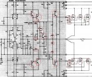
Anyways I would check all the part in the picture that are circled red out of circuit (aka remove) exept resistors. oh and check the fuses.
BTW I would remove the primary fuse and use a 60W lightbulb for saftey of blowing up more stuff (cheap current limiting)
...Anyways I would check all the part in the picture that are circled red out of circuit (aka remove) exept resistors. oh and check the fuses.
BTW I would remove the primary fuse and use a 60W lightbulb for saftey of blowing up more stuff (cheap current limiting)
Attachments
Truckee,
Read the manual. It should have a table of voltages expected at different parts of the circuit. It also has a picture of the back side of the PCB. With this info and a Variac, you can measure voltages at different parts of the circuit. This will help in your trouble shooting.
I hope the trouble with the bad channel is not in the 4 input jfet transistors. They must be matched and are no longer available -- except at a high price from Erno Borbely in Germany. The other transistors are fairly common.
The PS for this amp has one bridge and small pair of caps for both PCBs but has a separate bridge and large PS caps for each channel. The PCBs run at ~75VDC, the output section at ~65VDC.
Thanks everyone for helping!
I have checked all fuses and they are OK. Next job will be to pull the PCBs and heat sinks off the chassis so I can get at the points I need to measure and as necessary take any parts out for testing. Using a lightbulb to limit current draw is a pretty good technique I haven't used in a long time. Reminds me of the Nelson Pass Zen lightbulb amp.
Dick West: Glad to get your input. The only manual I have is what was on the hafler.com website, and I only realized today that on the picture of the non-component side of the PCB (I think it is a double sided board), voltages for critical points are shown. It will be a little work figuring out just where those points are on the more accessible component side, and even then without pulling the board/heatsink assembly off the chassis, it would be extremely difficult and dangerous getting a probe to those points. If anyone has a better idea getting those measurements, I'm all ears. I did see in the manual that I should have 65v for output and 75 for the input section, but I am only measuring 64 and change for both. and not sure why, or for that matter why one channel seems OK. Could be both channels aren't working properly, but one is much worse than the other.
I'll keep at it and report back. Thanks again everyone.
Hi Marshall,
If your voltages are close, the power supply for the input may not be running. You are getting supply voltage from the two diodes. Check to make sure one or both are not shorted.
Still, the amp should run. Take your voltage measurements from the component leads and solder terminals on the board edges. Your voltages seem to be varying a lot. Try to measure the voltage across R15 to ensure the front end is running. R34 or R35 may have gone open. Also watch those electrolytic caps. If the amp was run hot, they may fail (taking them out of circuit or leaking).
-Chris
Anatech,
I presume you mean the two diodes separating the two power supply rails on the input pcb's (separating what should be the 65 and 75 vdc lines). I checked and they are not shorted, which is good. I have pulled the heatsink away from the chassis so I can measure voltages, and will pull out the scope and sig generator and do some signal tracing. That will take a day or so with all the other stuff that keeps getting in the way!
Thanks,
Marshall
Hi Marshall,
-Chris
Yup. That's good. Power will feed from the LV supply back to the front end if the front end supply failed. If it did, you have to figure out why (shorted diodes would have done this).I presume you mean the two diodes separating the two power supply rails on the input pcb's (separating what should be the 65 and 75 vdc lines).
-Chris
Changed one of the diodes which seemed bad, but on testing it out of the circuit it looks OK. Finally disconnected power supply from all boards and transistors and measured DC voltage on the 75V bridge. The voltage was way low. Guess next I'll disconnect the AC lines from the transformer and see if it is OK. If it measures OK, then I'll test the caps and change the rest of the diodes in the bridge. Bummer.
I don't want to bother measuring voltages on the PCB until the rails are measuring OK.
I don't want to bother measuring voltages on the PCB until the rails are measuring OK.
Hi Marshall,
That's not what we really wanted to hear.
The filter caps are probably due for replacing anyway, and they aren't huge like the power amp section. Watch the small ceramic caps, they can short or become very leaky.
If you run the transformer with no load, it should not get very warm. If it does, then a winding may have shorted due to a problem in the rectifier or load.
You may have pulled the wrong diode if you didn't measure them all since th ewinding is a low DC resistance.
-Chris
Hi Anatech,
Really rotton day yesterday. Bad finger cut from a tree trimming job (tree fell on it) and then my temp controlled soldering station gave up the ghost. I am determined to either fix the amp or use it to build something different like a Zen amp.
I will get a solder wick and rebuild the power supply board with all new diodes and (small) caps and then see where we are. If I then have the right voltages, I guess the next step is to measure all the voltages on the PCB's and see where we are.
Thanks for hanging in with me. I'm sure there will be more questions once the rails are right again.
Marshall
Really rotton day yesterday. Bad finger cut from a tree trimming job (tree fell on it) and then my temp controlled soldering station gave up the ghost.
I am determined to either fix the amp or use it to build something different like a Zen amp.I will get a solder wick and rebuild the power supply board with all new diodes and (small) caps and then see where we are. If I then have the right voltages, I guess the next step is to measure all the voltages on the PCB's and see where we are.
Thanks for hanging in with me. I'm sure there will be more questions once the rails are right again.
Marshall
Hey Marshall,
Sorry to hear about your finger. That gets annoying while you try to work with small parts. Approach your work when you are calm.
My rule is : Beer (or wine) after! Maybe a bender if things go completely good or bad.
They sell good Oriental temp controlled stations. Mine is over 10 years old now. I went through more Weller stations than I care to remember. Never was impressed with Unger either. Mine cost about $120 CDN when I bought it. Digital temp display for set and actual tip temperature. I even calibrated my display.
-Chris
Well, I believe I have found a major problem. I unsoldered the AC winding leads for the front end power supply from the transformer and measured the AC voltage across the transformer secondary and then between secondary center tap (ground point)and the outer points on the secondary winding.
From ground to one side I got the proper voltage, but from ground to the other side there is an open circuit. I'll have to pull the transformer and see if there is a break in the wire from the transformer, but my guess is that I would have to rewind the transformer to fix the problem.
Any suggestions as to what to do now? I could look for a repacement transformer, or just gut the unit and use it to scratch build something else, or would having a transformer company rewind or repair the secondary be a viable solution?
At least the very nasty cut I receive on my finger has healed so I can manage a soldering iron again.
Marshall
Hi Marshall,
I'm glad to hear your finger is healing fine. Damaged windings are not so surprising given the problems the amp had. Look for a "pull" transformer that some members may have, or another used amp. The transformer can be rewound if you get a half decent price on the job. I would recommend against going with the cheapest quote. Someone with a good reputation is the best bet.
-Chris
- Status
- This old topic is closed. If you want to reopen this topic, contact a moderator using the "Report Post" button.
- Home
- Amplifiers
- Solid State
- help repairing Hafler xl280