I don't know what sort of input circuit the audio art has. If the shield ground (no RCAs plugged in) has ~0 ohms continuity to the non-bridging speaker wires, it may work.
There's no point in risking your home theater receiver. The old type receivers were more robust and easier to repair if they were damaged. Most people have one or two in a closet or in the attic that's why I generally ask about them.
There's no point in risking your home theater receiver. The old type receivers were more robust and easier to repair if they were damaged. Most people have one or two in a closet or in the attic that's why I generally ask about them.
I must be getting old. Although it's not important, when I said 'old', I meant an old two channel receiver from the 70's.
Well, if it's not going to be a significant loss if it's damaged, you can use it. You'd first want to connect a signal source to the crossover. You may be able to use an output of the receiver (from the tape monitor loop) and feed the output of the crossover into the receiver (into the tape monitor input) to confirm that the problem is duplicated when using the receiver.
Well, if it's not going to be a significant loss if it's damaged, you can use it. You'd first want to connect a signal source to the crossover. You may be able to use an output of the receiver (from the tape monitor loop) and feed the output of the crossover into the receiver (into the tape monitor input) to confirm that the problem is duplicated when using the receiver.
")
You'll need to make a test cable from an RCA cable. Cut one end off of the cable or solder wires to the center conductor of the RCA connector.
Leave the tape monitor output of the receiver plugged into the crossover input and set the receiver to FM and tune it to a station.
Before we go any further...
Does the receiver have an FM tuner that works?
Does it have a tape monitor loop?
Leave the tape monitor output of the receiver plugged into the crossover input and set the receiver to FM and tune it to a station.
Before we go any further...
Does the receiver have an FM tuner that works?
Does it have a tape monitor loop?
I'm assuming that you've made up the cable.
Set the receiver to the tape monitor that you're using (tape 1, 2...).
Set the volume to about the 8 o'clock position and touch the test cable to the center conductor for the RCA jack that you have the signal cable plugged into. Touch it to either the back of the RCA jack or to the point where the center conductor solders to the board. Do you get clean audio?
Which input are you using on the crossover?
ok, so now that I figured out how to do monitoring on the pioneer (helps to RTFM) I get clean sound, and no static. setup is mp3 player into "cd", "tape rec out" to sony front input, and rca test probe to "tape in". Then the other end of probe to the center pin of the front input on the sony.
no humm buzz static whitenose or hiss.
no humm buzz static whitenose or hiss.
ok:
Yes means noise/hiss
No means clean, but all no's had a background hum like a bad ground or a transformer hum
* means noise/hiss was louder
IC311 P2 yes P8 yes
IC421 P2 yes P8 yes
IC511 P2 yes P8 yes
IC621 P2 yes P8 yes
IC711 P1 no P7 no
IC301 P2 yes P8 yes
IC351 P2 yes P8 yes
IC401 P1 no P7 no
IC411 P2 yes P8 yes *
IC501 P2 yes P8 yes *
IC551 P2 yes P8 yes *
IC601 P2 yes P8 yes *
IC611 P2 yes P8 yes *
IC751 P1 yes P7 no
IC701 P1 yes P7 no
If you have trouble...
Apply enough solder to one row of pins to allow you to heat all of them at once.
With a small screwdriver, lift that side of the IC just slightly while the solder is molten.
Desolder that row of pins/pads (all should be free at this point).
Add solder and heat the other row of pins. Lift the IC off of the board while the solder is molten. Desolder the remaining pads.
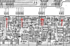
Solder pin 1 to any of the points indicated by the red arrow on the previously posted image. It's probably best if you follow the trace from pin 1 to another component and solder the wire at that point (instead of soldering directly to the pad for the IC). This will prevent you from damaging the pad.
Does it produce clean audio?
Does it produce clean audio?
- Status
- This old topic is closed. If you want to reopen this topic, contact a moderator using the "Report Post" button.
- Home
- General Interest
- Car Audio
- Help please