Something odd going.
Normally the opamps will run on a -/+ supply just like the main power IC.
It appears the negative rail is missing and I can't make out from the piccy where it goes or comes from.
You mentioned another board. What you need to do is switch off and trace on ohms pin 4 from the opamp and see where it goes... if it connects directly to the other pin 4's on the other IC's then trace from there. I would expect to see another part of a power supply somewhere to provide these rails perhaps with regulators.
I'm running out of time now but hopefully we will fix this... it's something really silly... it's just difficult working from piccys as you realise... but good fun and if you want to stick with it there's a good chance it can be fixed.
Is it worth asking in a new thread directly on the "solid state forum" if anyone has a circuit as that would make it easy.
Anyway the clue now is the missing rail on pin 4. Try and find where that is derived.
OK Mooly lets up stumps for now. Will post a pic of the second chip that I was speaking of. Not sure about the solid state forum, or any forum ") , have been running hard to keep up with you, so if you think it's a good idea I will do that. Thanks muchly for your input and free beer when in Sydney
, have been running hard to keep up with you, so if you think it's a good idea I will do that. Thanks muchly for your input and free beer when in Sydney  .
.
, have been running hard to keep up with you, so if you think it's a good idea I will do that. Thanks muchly for your input and free beer when in Sydney .Attachments
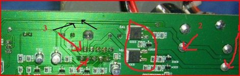
On the first piccy you posted where I labelled points 1 and 2 if you look at the PCB print from those large caps there is a spur running off to the left of the piccy along the top of the board. Think there's another spur running below it from the other cap.
They dissappear off the piccy at the left, but these will go to the regulators for the opamps etc so that's your clue... trace the -30 volts and see where is goes on that spur.
They dissappear off the piccy at the left, but these will go to the regulators for the opamps etc so that's your clue... trace the -30 volts and see where is goes on that spur.
The moo steak was excellent
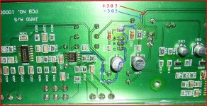
Have a look at this picture... I'm guessing the -30 volts goes to what I think will be a PNP transistor where I have marked A B C. I also notice the print "looks" discoloured... and you smelt burning.
What we will never know now is whether there was ever a problem with the output stage, or exactly what has happened. This front end is isolated in a way from the power stages, whatever happens there shouldn't affect this part of the amp. So all we can do is put right anything we find.
Can you measure the DC volts on A,B, and C. If I'm guessing the circuitry right from the picture then I would expect,
A. -12
B. -30
C. -11.4
Assuming I'm on the right track from the piccy then the glass component is a zener diode of 12 volts rating. If you measure the volts across the one next too it then that should also have +12 volts across, with +30 on the middle leg of the transistor and around +11.4 on the lower "leg". I think the transistor and probably zener are zapped... failure of the transistor would destroy the zener... however if there is -12 volts across it (point A) then it's OK. That leaves you with a zapped regulator transistor. Did it jump or was it pushed ? the only way to know is repair and see what happens with the possibility there may be a problem on that rail thats seeing the regulator off.
If right so far these are easily replaced very cheap parts... what's the device marking on the 3 legged transistor ?
Don't know if you have local availability of common bits but the zener is a 12 volt 0.4watt or 1.3 watt. Wattage not important as it's tiny, and you want small parts. Doesn't have to be surface mount, one with legs is fine. You can make zener values up so two 6.2 volts ones in series would be fine... and the ultimate voltage is not critical.
The transistor will be a PNP device, general purpose type with a Vce (Voltage rating collector to emmiter of at least 60 volts) and an Ic (collector current) of 500ma or more.
Which gives 100's of choices... do you have any shops etc that sell parts ?
Zeners like the top two in the list here,
http://tinyurl.com/2vqbvgl
transistor something like a 2n5401,
http://tinyurl.com/32pz8pp
however the pin outs are different (ABC in different order) so don't fit anything without checking first.
Attachments
Last edited:
This should be something like and might help you understand it, look at the first section, series voltage regulator. It's a classic "text" book design. Yours has a cap across the zener to help filter noise.
Series voltage regulator
this shows a positive regulator... which on yours is the working 12 volt side.
The faulty side is just the same except the diode is reversed and the transistor becomes a PNP type instead of an NPN. And of course all the voltages are reversed too.
Series voltage regulator
this shows a positive regulator... which on yours is the working 12 volt side.
The faulty side is just the same except the diode is reversed and the transistor becomes a PNP type instead of an NPN. And of course all the voltages are reversed too.
I'll me having some moo tonight, poor moos.
I have new output transistors, the discoloration is due to removing orginals and testing out of circuit - checked out OK but can try new ones, did check a diode and was showing no connection in circuit, did not want to send us on goose chase though. At work now will do checks tonight and report back
I have new output transistors, the discoloration is due to removing orginals and testing out of circuit - checked out OK but can try new ones, did check a diode and was showing no connection in circuit, did not want to send us on goose chase though. At work now will do checks tonight and report back
Another day, another dollar, if only...
Well "output transistors" that is my language, one NPN and one PNP, big ones, yes it is the abc spot marked the other is to the right, I removed both tested and reinstalled, even compared the readings with the new ones purchased, thought I would go with originals...
Well "output transistors" that is my language, one NPN and one PNP, big ones, yes it is the abc spot marked the other is to the right, I removed both tested and reinstalled, even compared the readings with the new ones purchased, thought I would go with originals...
- Status
- This old topic is closed. If you want to reopen this topic, contact a moderator using the "Report Post" button.
- Home
- Amplifiers
- Chip Amps
- Help noob fix sub amp