Hi everyone, I should have found this forum earlyer, I am a complete beginner and this forum is populated by very knolegable people so much that I can barely undersand the gergon.
I recently purchased a PWM + SMPS from http://www.cadaudio.dk.
The board is a D1000ASW Digital Amplifier + SMPS, the board can be seen from this link http://www.cadaudio.dk/pwmaudio_en.htm
I say I should have found this forum earlier because there has been already some bad press about the company and mr karsten madsen
CAD AUDIO DK
Røjlevej 8
DK - 5935 Bagenkop
Denmark
Phone/Fax:
(+45) 38 33 40 48
E-mail :
km_cad@yahoo.com
however I can only accuse them of providing no after sale customer support at all, as I have tried to contact mr k madsen for a month now and I have received no reply to emails, and no one answer the telephone.
The fact is that I have damaged the board myself by a stupid mistake, so at the end of the day I dont know if the board ever worked at all, but I shall assume it did, so now I have to try and fix it.
All I have understood of this is that, if I was pluggin in 240V and a balanced audio input signal at one end, a 1Kw would have come out at the other end, and it sounded quite amazing that I could do that with a mere 600 grams.
Any way, cutting al long story short, I have connected the board, but I forgot to plug in an additional module, which it was like a termination board that nested into a soket on the main board.
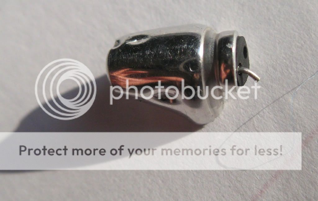
Power up and BANG! a little condenser went off, and it took with it also a tiny little plastic component just few millimiters across.
Now the little condenser has no number on it and I dont know what the other component is and were to find a replacement.
Also i dont know if my mishandling also caused other damages, but despite all, the rest seems to be ok at least apparently
I attach a pdf with pics of the components if someone could give me some advice on how to solve the situation it would be great, but I would not mind to pay someone and get the job done as well by someone more qualified than me, so please get in touch.
[-_-]
I recently purchased a PWM + SMPS from http://www.cadaudio.dk.
The board is a D1000ASW Digital Amplifier + SMPS, the board can be seen from this link http://www.cadaudio.dk/pwmaudio_en.htm
I say I should have found this forum earlier because there has been already some bad press about the company and mr karsten madsen
CAD AUDIO DK
Røjlevej 8
DK - 5935 Bagenkop
Denmark
Phone/Fax:
(+45) 38 33 40 48
E-mail :
km_cad@yahoo.com
however I can only accuse them of providing no after sale customer support at all, as I have tried to contact mr k madsen for a month now and I have received no reply to emails, and no one answer the telephone.
The fact is that I have damaged the board myself by a stupid mistake, so at the end of the day I dont know if the board ever worked at all, but I shall assume it did, so now I have to try and fix it.
All I have understood of this is that, if I was pluggin in 240V and a balanced audio input signal at one end, a 1Kw would have come out at the other end, and it sounded quite amazing that I could do that with a mere 600 grams.
Any way, cutting al long story short, I have connected the board, but I forgot to plug in an additional module, which it was like a termination board that nested into a soket on the main board.
Power up and BANG! a little condenser went off, and it took with it also a tiny little plastic component just few millimiters across.
Now the little condenser has no number on it and I dont know what the other component is and were to find a replacement.
Also i dont know if my mishandling also caused other damages, but despite all, the rest seems to be ok at least apparently
I attach a pdf with pics of the components if someone could give me some advice on how to solve the situation it would be great, but I would not mind to pay someone and get the job done as well by someone more qualified than me, so please get in touch.
[-_-]
Attachments
Your descriptions don't give us a lot to go on. The link you have posted to the site does not work. It is possible that the board you forgot to connect was to convert ac to dc and you have applied ac to the board and hence the bang and smoke!
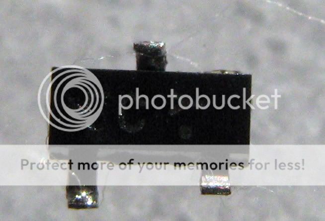
The top photo looks like it is a diode, but I can't identify the other item. You need to post more pics of the damaged board, and the board you did not fit.
The top photo looks like it is a diode, but I can't identify the other item. You need to post more pics of the damaged board, and the board you did not fit.
more pics 4
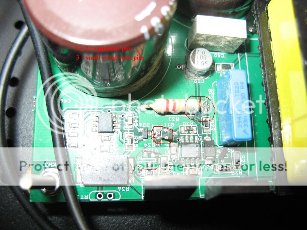
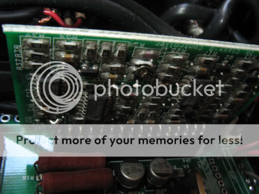
Component location
This marked in red is the location were the capacitor and the other component were soldered, you can still see the pins of the condenser (1 and 2) and the empty space of the other component (3)
the small gif I uploading probably wont show much details
Component location
This marked in red is the location were the capacitor and the other component were soldered, you can still see the pins of the condenser (1 and 2) and the empty space of the other component (3)
the small gif I uploading probably wont show much details
Attachments
manual
and finally, the manual with all the other infos can be downloaded from the company website http://www.cadaudio.dk/
the amp is the CAD D1000ASW - 1000W/4 ohms PWM amplifier + SMPS
I waiting for your reply...
and finally, the manual with all the other infos can be downloaded from the company website http://www.cadaudio.dk/
the amp is the CAD D1000ASW - 1000W/4 ohms PWM amplifier + SMPS
I waiting for your reply...
Unfortunately the pics are too small to see properly. You can load larger pictures if you use photobucket and use the IMG link to direct link to the photo. Like so.
An externally hosted image should be here but it was not working when we last tested it.
hope this work, component location
http://i595.photobucket.com/albums/tt38/simonomis123/components_location.jpg
http://i595.photobucket.com/albums/tt38/simonomis123/components_location.jpg
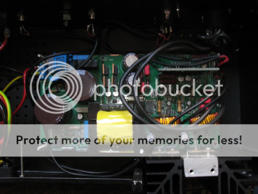
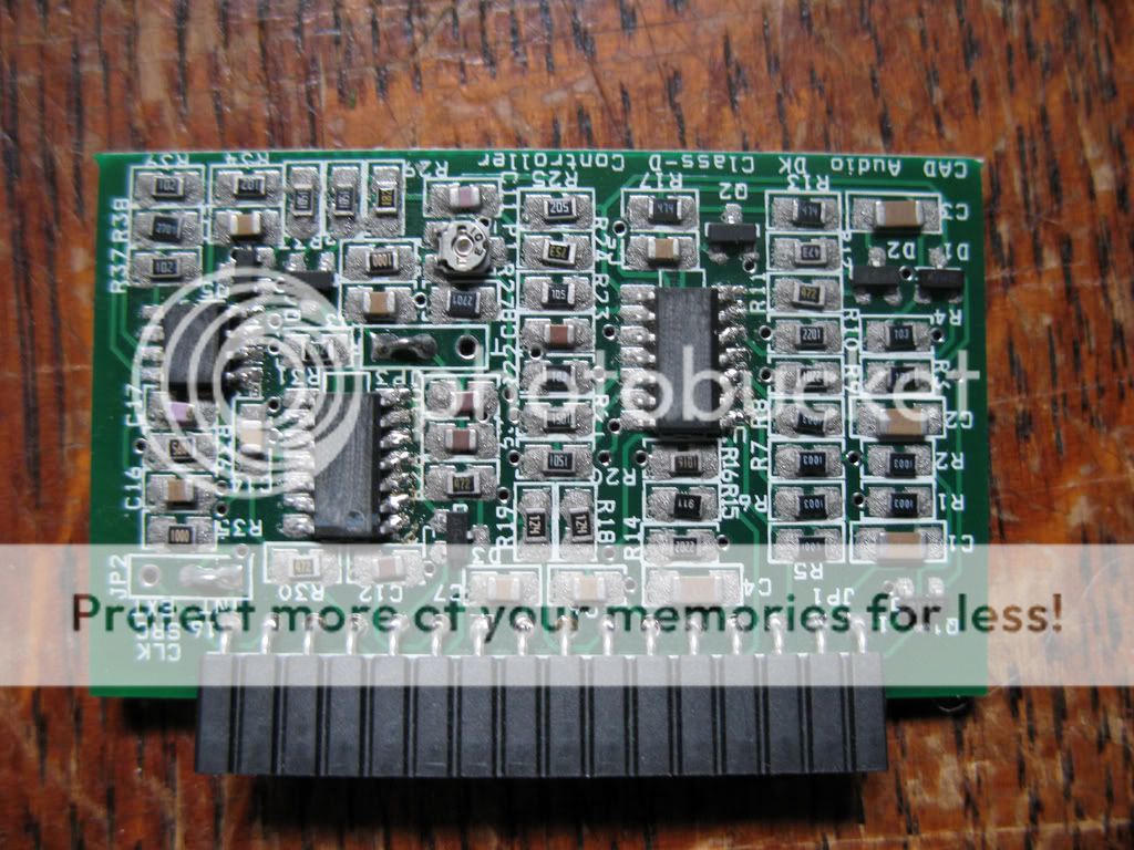
This is the board
http://i595.photobucket.com/albums/tt38/simonomis123/500W_feedback_controller.jpg
http://i595.photobucket.com/albums/tt38/simonomis123/500W_feedback_controller.jpg
An externally hosted image should be here but it was not working when we last tested it.


Did you install insulators between screws and transistor tabs? I can only see the insulator between transistor and heatsink in the picture, but maybe this is just because it's blurry.
The missing board is probably not the reason it blew.
It does look pretty strange though how that capacitor was installed. Tacked on as an afterthought? I'm not sure I'm seeing correctly but it looks to me like the capacitor might have been installed incorrectly.
Point 1 looks like positive bus voltage and point 2 like primary negative. Maybe the capacitor was supposed to go between 2 and the other side of the big resistor which should be positive for the switching chips. It would explain the explosion: 300V DC on a 16V or so cap... But I could be wrong on this one.
I guess it isn't possible to make out the voltage rating of the blown cap any longer...
The blown off transistor looks like a gate turnoff helper. I couldn't make sense of the pinout at first but now I get it - it's supposed to be installed turned just like Q9 is!
- Status
- This old topic is closed. If you want to reopen this topic, contact a moderator using the "Report Post" button.
- Home
- Amplifiers
- Class D
- Help needed - Novice PWM Amp - not working