Fred,
You also mentioned "shielded wire", for the inputs I assume. And you said the shield was grounded at one end only. From where to where does the shielded wire run? And does it contain a separate (from the shield) signal ground conductor? And where did you ground the shield?
I guess maybe we could assume that you used shielded RCA cable(?), meaning that the shields are the input grounds that you connected together at the isolated RCA jacks and then ran to the star ground. Is that correct?
A photo or two, and a schematic that also explicitly shows the ground conductors, might really help!
Cheers,
Tom
Last edited:
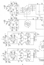
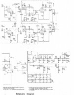
First let me include the schematic of the integrated amp so that there will be some reference to the components for the sake of discusssion. There were some tweaks in component values, but overall circuit remains the same.
Sadly to say, this happens to both channels. I removed the input tube one channels at a time. Effectively I was running single channel, same symptom to both. Whatever I did wrong, I did it twice") When the input is open (nothing plugged into it), it is totally quiet. Once I put in a shorting male RCA plug or a turntable to the input, the hum appears.
When the input is open (nothing plugged into it), it is totally quiet. Once I put in a shorting male RCA plug or a turntable to the input, the hum appears.
FWIW, the circuit star ground that I mentioned is where all the local star grounds merged. Local star grounds are power supply ground, output tube ground, LTP ground, AF ground, line stage ground, and the phono stage ground. It is point to point wiring.
The phono input doesn't have an input cap, but the line stage does.
The shield cable is a coaxial cable, but I only use the coax's ground for shielding. I tied the RCA's ground tabs together and run a wire from this "combined" ground to the star ground. One side of the shield cable is also connected to this combined ground spot. I will upload a picture of input wiring later once my daughter brings back the camera. Sorry for my lousy description, it is so true that one picture is better than thousands words. I will try to get one asap.
When it works, grounding scheme seems to be so easy, but when it hums, it is like hell
Thanks all for your help!!
Hi Globulator,We should discount the cable then!
Is it the same on each channel?
Does it still do it without the input tubes?
Can you confirm the RCA ground goes to the phono PCB ground?
Are the input capacitors working?
Sadly to say, this happens to both channels. I removed the input tube one channels at a time. Effectively I was running single channel, same symptom to both. Whatever I did wrong, I did it twice
When the input is open (nothing plugged into it), it is totally quiet. Once I put in a shorting male RCA plug or a turntable to the input, the hum appears.FWIW, the circuit star ground that I mentioned is where all the local star grounds merged. Local star grounds are power supply ground, output tube ground, LTP ground, AF ground, line stage ground, and the phono stage ground. It is point to point wiring.
The phono input doesn't have an input cap, but the line stage does.
Hi Tom,Fred,
You also mentioned "shielded wire", for the inputs I assume. And you said the shield was grounded at one end only. From where to where does the shielded wire run? And does it contain a separate (from the shield) signal ground conductor? And where did you ground the shield?
I guess maybe we could assume that you used shielded RCA cable(?), meaning that the shields are the input grounds that you connected together at the isolated RCA jacks and then ran to the star ground. Is that correct?
A photo or two, and a schematic that also explicitly shows the ground conductors, might really help!
Cheers,
Tom
The shield cable is a coaxial cable, but I only use the coax's ground for shielding. I tied the RCA's ground tabs together and run a wire from this "combined" ground to the star ground. One side of the shield cable is also connected to this combined ground spot. I will upload a picture of input wiring later once my daughter brings back the camera. Sorry for my lousy description, it is so true that one picture is better than thousands words. I will try to get one asap.
When it works, grounding scheme seems to be so easy, but when it hums, it is like hell
Thanks all for your help!!
Attachments
Maybe it's my eyes but I see the cathode resistor going from ground to the input, then a black wire going from the input to the cathode - but no connection to the RCA ground..
Not knowing the pinout etc I could be wrong though, but either way I see no ground for the socket, and the grid should be grounded from the same bit as the cathode resistor ground.
This is assuming a grounded grid as implied by the low R resistor from input to ground - or is that just a load?
Not knowing the pinout etc I could be wrong though, but either way I see no ground for the socket, and the grid should be grounded from the same bit as the cathode resistor ground.
This is assuming a grounded grid as implied by the low R resistor from input to ground - or is that just a load?
wires through holes
If the current flows down a wire and back through a matching wire to run through a metallic or conducting hole then the two current fields cancel and the metal has little effect.
If current flows down a single through a hole and returns by another route then there is no current field cancellation. "Current transformer"
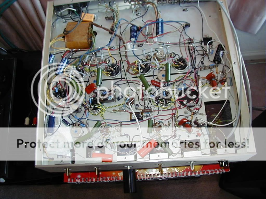
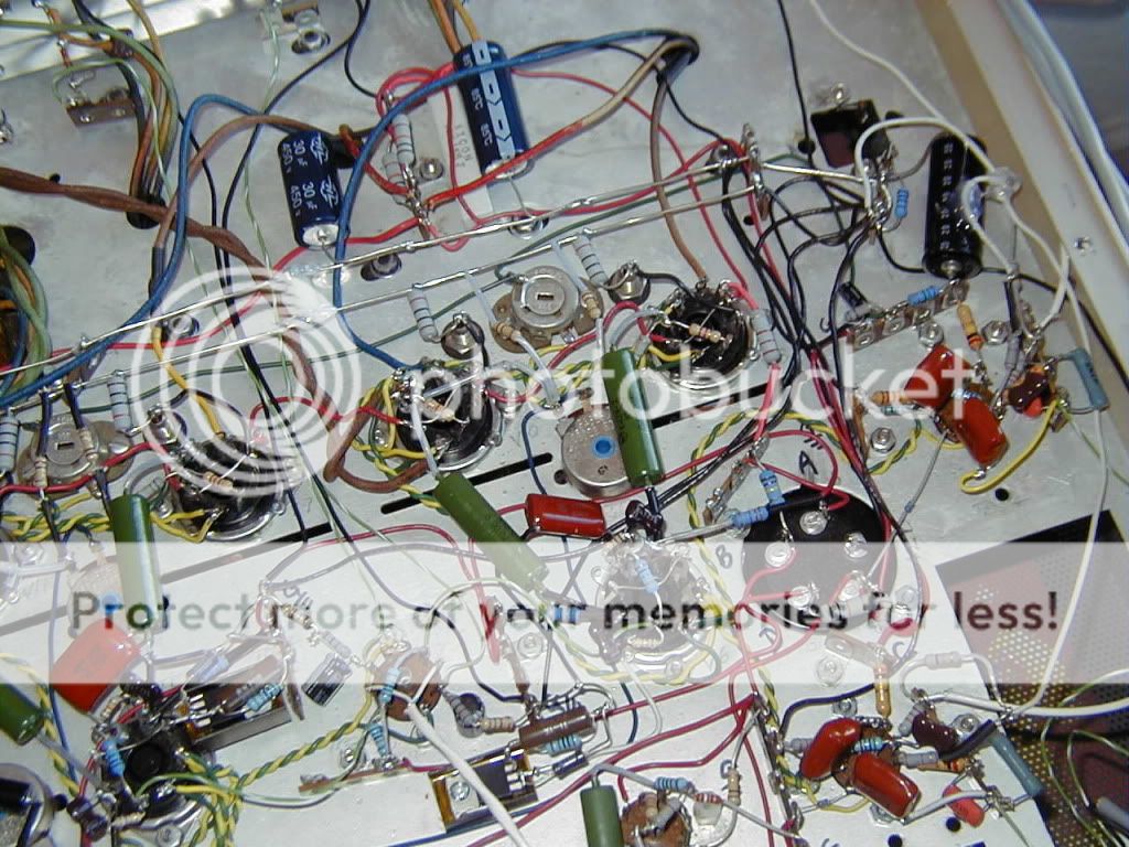
The wiring used to be a little neater, but since the last few experiments in trouble shooting and ran out of black wire, it;s kind of a little mess to follow. So, here are my attempt to explains the pictures:
Pic #1. This is overview of the nest layout. The inputs are at the back, and the phono
sockets are the rightmost socket and the bottom right.
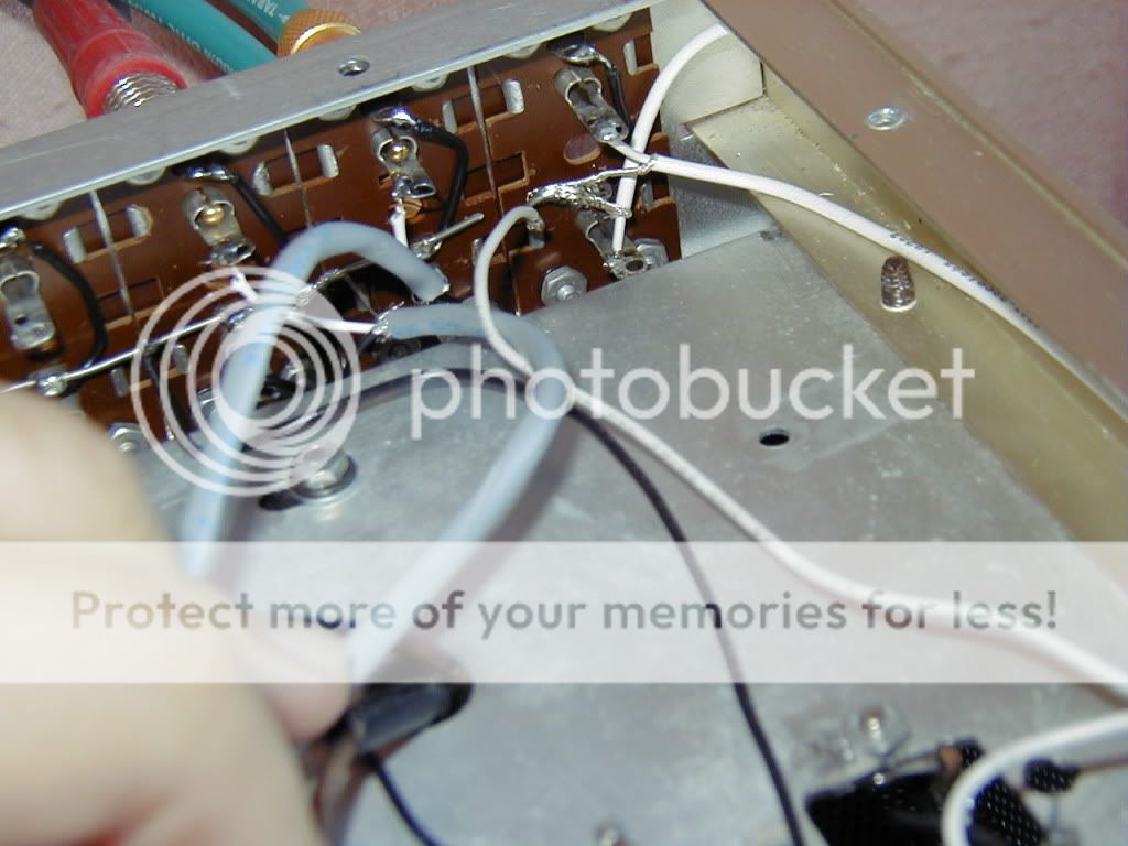
Pic #2. A close up of the input RCA's. The grey shield wires are for the line stage input.
The phono inputs have white shielded cable. The shield is soldered to the
(signal) ground. **Should I solder the shield to the chassis instead??
The grey cables are connected to the selector, and the phono cables (white)
are connected to pin 7 of the sockets.
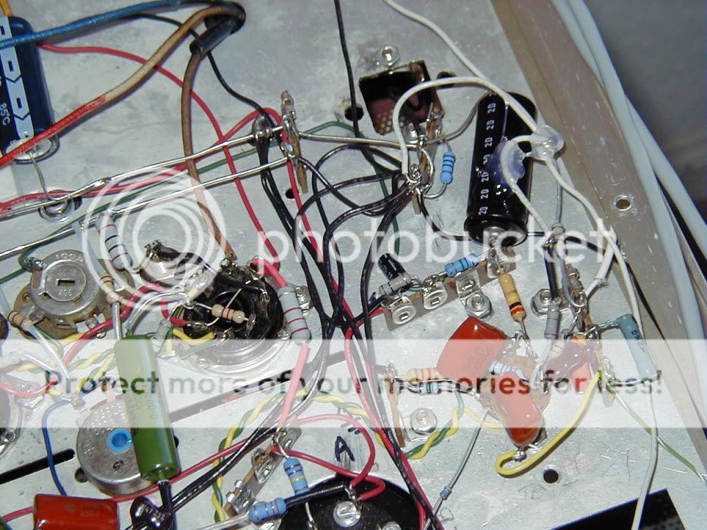
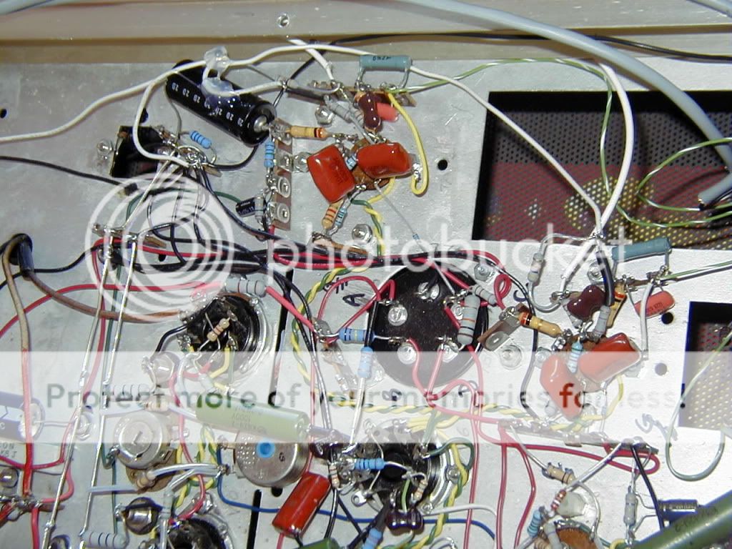
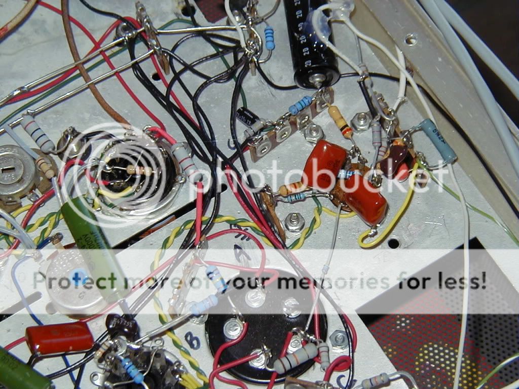
Pic #3,6 Semi-close up of one phono channel. Notice that I am using the 12AX7
instead of the 12EW7 as in the schematic. At the right of the picture, you can
see the white coax cable going into pin the tag board and then a 22K into
the grid (pin 7). Currently, I have the grounds of the first RIAA stage (pns
6,7,8) separated from the second stage (pins 1,2,3). The first stage's 47K
(load resistor) and the 2.4K (cathode) joined and then goes to the star ground.
The second stage's ground are joined at the tag board which is connected
to the star ground.
Pics #4,5 are 2 different views of the 2 phono sockets.
Loren, the schematic is in post #22 in zip. Here are the schematics
in JPG form.
Andrew, good thinking. I will apply that to the scenario of no input and the shorted input to see I can figure out how the current flows.
Thanks!!
Pic #1. This is overview of the nest layout. The inputs are at the back, and the phono
sockets are the rightmost socket and the bottom right.
Pic #2. A close up of the input RCA's. The grey shield wires are for the line stage input.
The phono inputs have white shielded cable. The shield is soldered to the
(signal) ground. **Should I solder the shield to the chassis instead??
The grey cables are connected to the selector, and the phono cables (white)
are connected to pin 7 of the sockets.
Pic #3,6 Semi-close up of one phono channel. Notice that I am using the 12AX7
instead of the 12EW7 as in the schematic. At the right of the picture, you can
see the white coax cable going into pin the tag board and then a 22K into
the grid (pin 7). Currently, I have the grounds of the first RIAA stage (pns
6,7,8) separated from the second stage (pins 1,2,3). The first stage's 47K
(load resistor) and the 2.4K (cathode) joined and then goes to the star ground.
The second stage's ground are joined at the tag board which is connected
to the star ground.
Pics #4,5 are 2 different views of the 2 phono sockets.
Loren, the schematic is in post #22 in zip. Here are the schematics
in JPG form.
Andrew, good thinking. I will apply that to the scenario of no input and the shorted input to see I can figure out how the current flows.
Thanks!!
Attachments
Thanks!
The schematic shows the jacks grounded, but does not differentiate the type of ground or the mechanism used.
Shielded wire is not designated on the schematic, so again, it is hard to determine how this is really wired.
I guess, for clarity's sake it would be ideal if that was noted on the schematic.
Pic #2. A close up of the input RCA's. The grey shield wires are for the line stage input.
The phono inputs have white shielded cable. The shield is soldered to the
(signal) ground. **Should I solder the shield to the chassis instead??
The grey cables are connected to the selector, and the phono cables (white)
are connected to pin 7 of the sockets.
Pic #3,6 Semi-close up of one phono channel. Notice that I am using the 12AX7
instead of the 12EW7 as in the schematic. At the right of the picture, you can
see the white coax cable going into pin the tag board and then a 22K into
the grid (pin 7). Currently, I have the grounds of the first RIAA stage (pns
6,7,8) separated from the second stage (pins 1,2,3). The first stage's 47K
(load resistor) and the 2.4K (cathode) joined and then goes to the star ground.
The second stage's ground are joined at the tag board which is connected
to the star ground.
As far as I see you are calling things shields - but they are not shields, they are grounds. a Shield is a 3rd metal sheath that is clearly absent!
Ok - so you have the white phono wires consisting of signal (inner) and ground (outer). You connect the inner and outer at the RCA plug, and the inners at the other end to the tag strips -
- what are the grounds (outer) of the white phono wires connected to?
Yeah, this is pretty much true for most of the 50's and 60's tube schematic - no indication of the grounding scheme to use. The 2080 was a revision of the amp that I am rebuilding - an Eico ST-70. I do have the construction manual of the ST-70.
In the original amp, it used 2 wire power cable and the chassis was the common ground, i.e. the signal and power supply grounds were either soldered to a tag board which had the tap bolted to the chassis or directly to the chassis. I replaced the power cable with the 3 wire IEC cable and had the earth tightly soldered a tap that is bolted to the chassis. I also redid the star grounding as I described earlier.
The original amp used shielded cable for all inputs. I think it made sense to this amp as the input jacks and the selector are very far away. So, I used shielded cable, too. The major differences are I used multiple shielded cables where the original was like a snake cable which have many wires inside.
The line stage works perfectly. It is dead quiet, I have an external phono preamp and a DAC connected, no hum or whatsoever. The only trouble is the internal phonon stage. Look at picture #2, the phono input is at the far right. This cable connects the RCA +ve to the pin 7, and the shield is connected to the ground at the input, but that is the other end is NOT connected. You can see the shield was cut off in one end in picture #3 - the white wire connected to a tap of a tag board which has a 22K grid stopper to pin 7. In other words, the shield is not used as signal ground and is only connected to ground in one end. It is only for shunting the RF noise - at least that's my thinking and intent.
I have been thinking about what Andrew and Tom said. When the input is shorted or loaded with the cartridge, the resistance between the input and the signal ground becomes so low that current flows into the grid?? Maybe the phono grounds should be connected to somewhere else instead of the star ground ??
I was writing my post while you replied. I think I used the wrong term.As far as I see you are calling things shields - but they are not shields, they are grounds. a Shield is a 3rd metal sheath that is clearly absent!
Ok - so you have the white phono wires consisting of signal (inner) and ground (outer). You connect the inner and outer at the RCA plug, and the inners at the other end to the tag strips -
- what are the grounds (outer) of the white phono wires connected to?
I am using the ground of the shielded cable is a screen to protect the signal wire from the RF noise. The way I connect this screen is how Morgan Jones suggested in Building Valve Amplifiers - connect one end only on the source side. This shielded cable doesn't carry the signal ground. I hope this will clarify some of the confusion due to unclear description.
Thanks,
Fred,
The white phono cable has only a single wire inside, unlike the grey shielded line input cable, which has two wires AND a shield.
I would replace the white shielded wires (from the phono inputs) with two-conductor shielded cables, just like the grey ones you used for the line inputs.
I would disconnect the phono input RCA jacks' ground tabs from whatever they are now connected to and then connect each one only to the ground conductor inside its new shielded two-conductor cable, and connect the shields to (probably the chassis), on that end only, leaving as little as possible unshielded signal or ground wire exposed, but keeping the signal and ground wires in each pair as close to each other as possible for as long as possible, and twisting together the exposed (unshielded) lengths of each signal and ground wire pair if there is enough wire length there (but maybe not adding extra length just to be able to twist them together).
The new ground conductors inside the two new shielded two-conductor phono input cables should then be connected to the ground ends of the resistors that go from their respective grid inputs to ground, right at the resistor (assuming I'm reading the schematic correctly).
And if possible, each phono input ground wire should stay as close as possible to the signal conductor that goes to the grid and then stay as close as possible to the grid-to-ground resistor's lead and the resistor until it gets to the other end of the resistor, where it will be soldered. If you can twist together the exposed ground and signal wires, there, even though they are as short as possible while still being able to run right next to each other, do it.
Tom
Last edited:
This shielded cable doesn't carry the signal ground
Oh yes it does - you connected it to signal ground at the RCA
.The outer wire serves two purposes - signal ground and RF/AF shielding.
Connect the outer part of the white wire to the ground part of the R7/R8 cathode resistors of the phono tubes.
This is the cause of your hum - no signal ground.
It does have a signal ground. It is another white cable in picture #2. I ran out of black wire, so I used a white color insteadOh yes it does - you connected it to signal ground at the RCA
The outer wire serves two purposes - signal ground and RF/AF shielding.
Connect the outer part of the white wire to the ground part of the R7/R8 cathode resistors of the phono tubes.
This is the cause of your hum - no signal ground.
This wire is connected to the grounds of R1, R2, R7, and R8 at one point which connects to the star ground.Combining what you said and Tom's suggestion, I maybe making a mistake to tie the 2 input grounds together and exposing the ground wire like what I did. I will change the phono's input wire and report the result later.
Thanks!!
Fred,
A minor change:
After reading the article at http://www.diyaudio.com/forums/diya...udio-component-grounding-interconnection.html , I now think you should connect each of the shields of the two-internal-conductor shielded input cables directly to the main star ground point (instead of to the chassis), with a separate wire from the upstream end of each shield to the star point.
Cheers,
Tom
Kudos to everyone who helped tackle my problem. I am pleased to report that Tom's suggestion did the trick.
Since I wanted to know exactly which was the major mistake that I made, I took the time to make incremental changes and used a signal tracer to test the result. I concluded that my mistake was the act that I tied the input's ground together. This scheme doesn't affect the high level inputs (no hum at full volume) but not so to the phono inputs. After I cut the input "common ground" and ran 2 separate ground wires to the star ground, the hum was reduced greatly. Anyhow, Tom's scheme was the final touch.
Again, a big thank you!!!
- Status
- This old topic is closed. If you want to reopen this topic, contact a moderator using the "Report Post" button.
- Home
- Amplifiers
- Tubes / Valves
- Help! ground hum