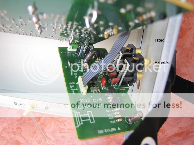
Hello! For many examples of taking audio feeds before op amps and transistor stages ( either amplification or muting) I'd recommend you look in on the Lampizator ( Lukasz Fikus Lampizator). I've worked on a few Kenwood players but always DP-xx90's. Looking at the board it's a certainty that you have both muting transistors and capacitors in the audio signal path. Might be worth lifting the lead from the board and taking your L&R direct from there? The DAC is a Philips TDA1547 - I know Lukasz did some work on this chip in one of his projects. Good luck!
There's a fair bit about the DAC7 (TDA1547) as its a nice sounding chip. It should be possible to take the output from the dac via a single opamp stage and DC blocking caps straight to the output. Could do with a manual really ;-)
If you wanted to go mad, you could bypass the built in opamp I/V on the DAC and build a separate I/V ;-)
If you wanted to go mad, you could bypass the built in opamp I/V on the DAC and build a separate I/V ;-)
That's probably the best advice to be fair. Decent Opamps with their local decoupling caps will significantly help. Also check for dc blocking caps after the opamps but before the muting circuit. Swapping these for mkp type will help. If you take a picture of the pcb with the dac and opamps, we should be able to point out the candidates for upgrade ;-)
Hi, UV101
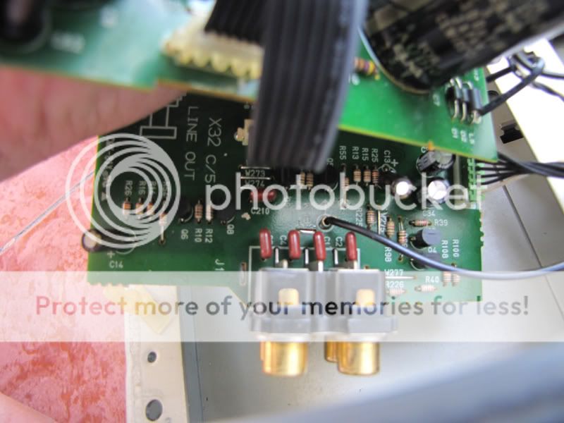
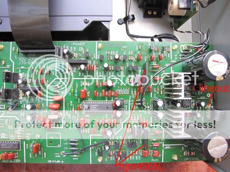
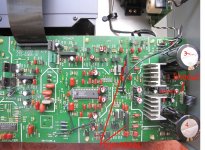
I attach herein more photos of the player for your reference. My player uses two output opamps named njm4565l, one for left channel and one for right channel. output capacitors are 47uF/50V brown elna ones as you can see in the previously attached photos. filter chip is NPC sm5840cp.
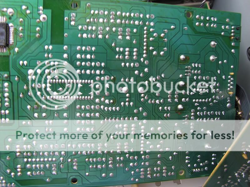
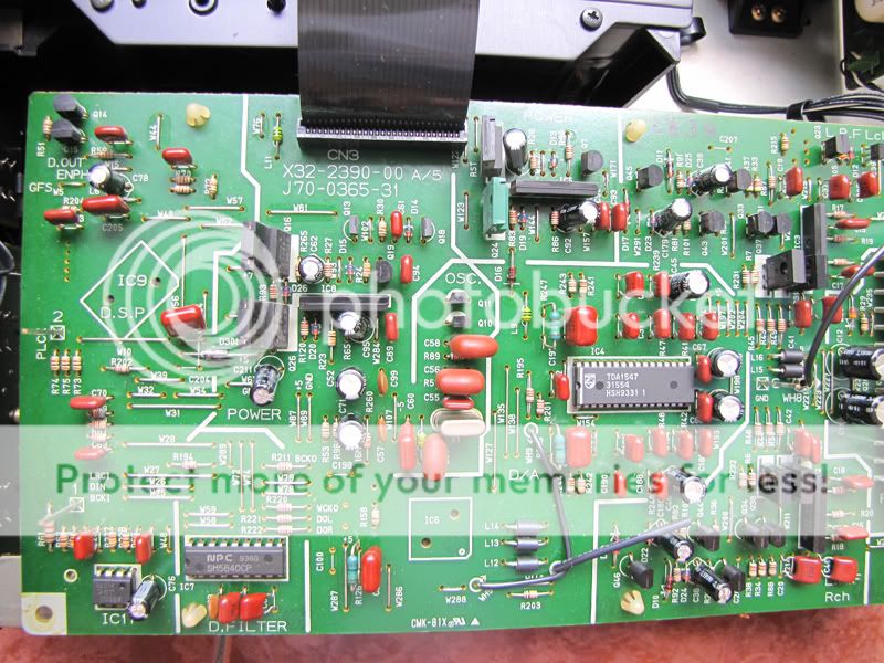
I attach herein more photos of the player for your reference. My player uses two output opamps named njm4565l, one for left channel and one for right channel. output capacitors are 47uF/50V brown elna ones as you can see in the previously attached photos. filter chip is NPC sm5840cp.
Which opamps should i use to replace the old ones and what capacitance for the decoupling caps? As the current opamps are sip8 type, so i will have to make two adaptor sockets for new ones. I have fortunately found a schematics for such adaptor on the internet.
By the way, should i remove the mute transistors?
By the way, should i remove the mute transistors?
Last edited:
Dear SoNic_real_one ,
Which opamps should i use to replace the old ones and what capacitance for decoupling caps? By the way, should i remove mute transistors?
Which opamps should i use to replace the old ones and what capacitance for decoupling caps? By the way, should i remove mute transistors?
I've used Burr Brown OPA627BP's - big improvement over the normal ones used in CD players, but there is plenty of choice. For the minimum effort, Sonic's input is fine. Marantz used the TDA1547 with their HDAM system in the CD-17, which turned out to be a discrete transistor stage and sounds great. This is closer to UV101's suggestion, but involves more reading & work!
I'd go along with substituting the opamps too but you need to exercise care, particularly if you need to make up adapter.
Don't take it for granted that it will be stable without at least some basic tests,
http://www.diyaudio.com/forums/anal...u-have-checked-see-its-stable-havent-you.html
I would perhaps suggest trying OPA2134 or OPA2604
Don't take it for granted that it will be stable without at least some basic tests,
http://www.diyaudio.com/forums/anal...u-have-checked-see-its-stable-havent-you.html
I would perhaps suggest trying OPA2134 or OPA2604
these are also available. 2pcs Single or Dual opamp SMD DIP8 to DIN8 Adapter | eBay
My personal fav's are LM4562,LME49720 & LME49860 which in fact are believed to all be the same opamp (check the datasheets!!!)
Anyone found a manual???
My personal fav's are LM4562,LME49720 & LME49860 which in fact are believed to all be the same opamp (check the datasheets!!!)
Anyone found a manual???
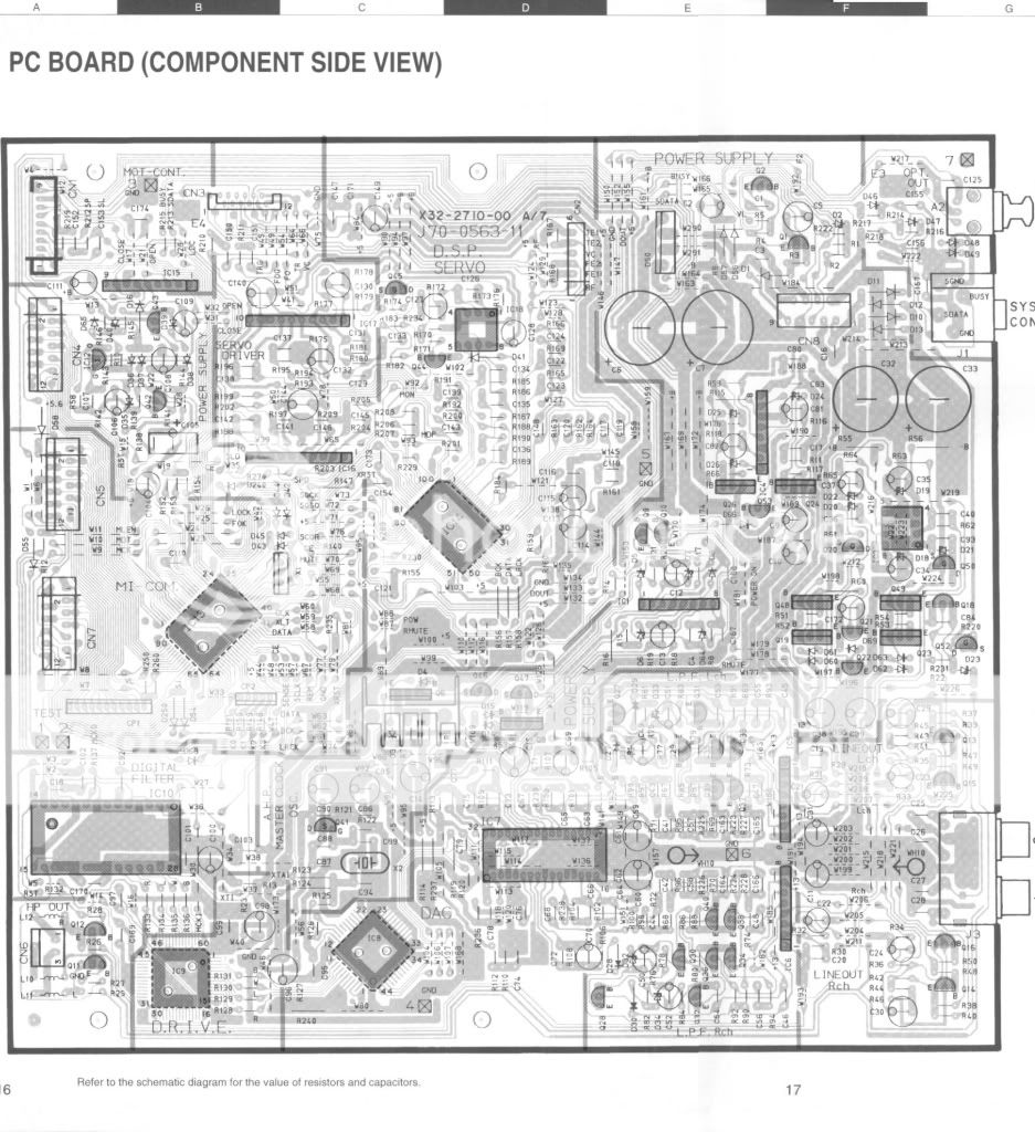
1 & 2 post regulator caps (probably on +/- 12v)Black gate, Rubycon ZA or ZLH
3 & 4 Smoothers for the regs on the heatsinks - will be for analogue rails mentioned above) Mundorf SI ot other high capacitance low ESR
5 & 6 DAC analogue Black gate, Rubycon ZA or ZLH
7 & 8 DAC digital Solid polymer ultra low ESR Oscon SEPC or Nichicon LE
9,10,11 & 12 analogue filter Black gate, Rubycon ZA or ZLH
OPamps all swapped for LM4563 or similar (assuming duals which I've not looked up so please check)
There is also another opamp in between the regs. This is probably a buffer and therefore in the audio path. this could also be swapped and the local decoupling swapped to Black gate, Rubycon ZA or ZLH
There are a host of other caps in the digital domain that could do with being swapped for Solid polymer ultra low ESR Oscon SEPC or Nichicon LE
Most of the remianin caps left of the DAC will be digital.
General rukw of thumb is to sue std electrolytics on any analogue rails and solid polymer electrolytics on digital.
I normally use anywhere between 220uF and 470uF for local decoupling.
Use the datasheet for all chips to establish which pins are which.
Please remember this is just guess work based on experience. The only way I can tell for sure is with the service manual.
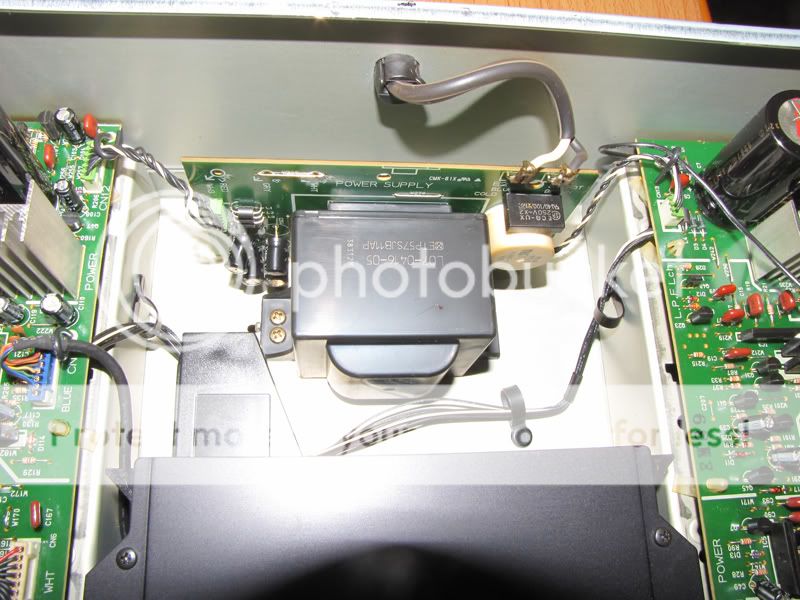
Not a bad looking layout either (other than the big PSU near the output satges which has arguments both for and against!)
3 & 4 Smoothers for the regs on the heatsinks - will be for analogue rails mentioned above) Mundorf SI ot other high capacitance low ESR
5 & 6 DAC analogue Black gate, Rubycon ZA or ZLH
7 & 8 DAC digital Solid polymer ultra low ESR Oscon SEPC or Nichicon LE
9,10,11 & 12 analogue filter Black gate, Rubycon ZA or ZLH
OPamps all swapped for LM4563 or similar (assuming duals which I've not looked up so please check)
There is also another opamp in between the regs. This is probably a buffer and therefore in the audio path. this could also be swapped and the local decoupling swapped to Black gate, Rubycon ZA or ZLH
There are a host of other caps in the digital domain that could do with being swapped for Solid polymer ultra low ESR Oscon SEPC or Nichicon LE
Most of the remianin caps left of the DAC will be digital.
General rukw of thumb is to sue std electrolytics on any analogue rails and solid polymer electrolytics on digital.
I normally use anywhere between 220uF and 470uF for local decoupling.
Use the datasheet for all chips to establish which pins are which.
Please remember this is just guess work based on experience. The only way I can tell for sure is with the service manual.
Not a bad looking layout either (other than the big PSU near the output satges which has arguments both for and against!)
Attachments
Dear UV101
NJM 4565L is dual opamp. According to the opamp datasheet and the CDP's board layout, the audio path from the njm4565L opamps seem to be as follows:
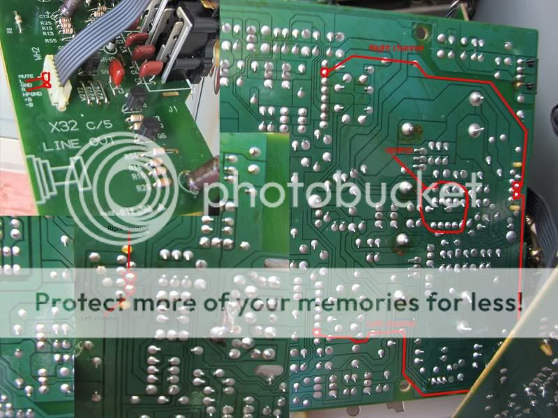
Therefore, the opamp you mentioned may have nothing to do with the audio path. I think this opamp and the pair of large 3300uF elna capacitors are related with power supply section for the digital and analog stages.
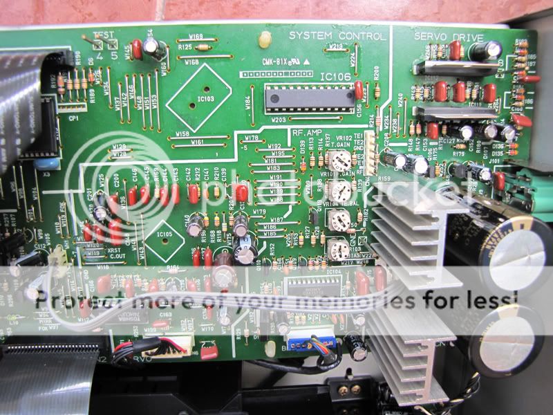
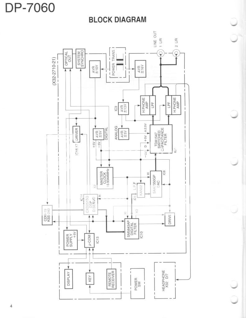
Unfortunately I don't have the player service manual of the player. I have found a service manual of Kenwood dp-7060 which uses the same DAC with my player. The major difference of these players i notice is that my player has different boards for audio and servo-drive parts. I attach the 7060 schematics herein for your refence
Link for DP-7060 service manual:
http://www.hifi-manuals.com/Download/Kenwood/DP-7060-service-manual
NJM 4565L is dual opamp. According to the opamp datasheet and the CDP's board layout, the audio path from the njm4565L opamps seem to be as follows:
Therefore, the opamp you mentioned may have nothing to do with the audio path. I think this opamp and the pair of large 3300uF elna capacitors are related with power supply section for the digital and analog stages.
Unfortunately I don't have the player service manual of the player. I have found a service manual of Kenwood dp-7060 which uses the same DAC with my player. The major difference of these players i notice is that my player has different boards for audio and servo-drive parts. I attach the 7060 schematics herein for your refence
Link for DP-7060 service manual:
http://www.hifi-manuals.com/Download/Kenwood/DP-7060-service-manual
Last edited:
I also prefer LME49720 but I don't have any in hand, so I use OPA2134 to swap the old opamps and find that the sound is better and clearer, a bit more detailed, more bass.
3 and 4 are "elna for audio" capacitors, so i decide to leave them alone.
4,6,7,8 I will replace with Sanyo oscon and 9,10,11,12 with Rubycon
3 and 4 are "elna for audio" capacitors, so i decide to leave them alone.
4,6,7,8 I will replace with Sanyo oscon and 9,10,11,12 with Rubycon
Last edited:
Link for Kenwood dp-7060 service manual
Download the Kenwood DP-7060 service manual for free - Hifi Manuals
Download the Kenwood DP-7060 service manual for free - Hifi Manuals
I found that manual too but as you say, the layout is different.
Definatley check that the caps I have identified are PSU decoupling. Trace them to the IC pin and use the datasheet to confirm. It is also important to replace the PSU decoupling on the filter and logic to solid polymer type as these are exceptionally low ESR.
Another general rule is to get the caps as close to the IC pin as possible. Often there will be a bypass cap of approx 100nF shunting trace noise to groundvery close. I ofter remove these caps and use the holes left for the new elco's then use smt 100nF across the pins of the new cap under the pcb.
With certain caps types, Black Gate for example, some have reported further improvments removing these 100nF caps. I guess its worth trying with and without.
Just thought of something else, there are 11 PSU rails to the tda1547 ( datasheet here ). Some of the rails will share single elco's but have multiple 100nF caps close to the pin. Personally I'd replace the 100nF with multiple elco's")
Definatley check that the caps I have identified are PSU decoupling. Trace them to the IC pin and use the datasheet to confirm. It is also important to replace the PSU decoupling on the filter and logic to solid polymer type as these are exceptionally low ESR.
Another general rule is to get the caps as close to the IC pin as possible. Often there will be a bypass cap of approx 100nF shunting trace noise to groundvery close. I ofter remove these caps and use the holes left for the new elco's then use smt 100nF across the pins of the new cap under the pcb.
With certain caps types, Black Gate for example, some have reported further improvments removing these 100nF caps. I guess its worth trying with and without.
Just thought of something else, there are 11 PSU rails to the tda1547 ( datasheet here ). Some of the rails will share single elco's but have multiple 100nF caps close to the pin. Personally I'd replace the 100nF with multiple elco's
Last edited:
I am not so good at English, please tell me what "elco's" means?
Electroylitic capacitor.
- Status
- This old topic is closed. If you want to reopen this topic, contact a moderator using the "Report Post" button.
- Home
- Source & Line
- Digital Source
- Help for Kenwood dp-7050 mod