Yes, I bought the ECM-40
For translation you can use Google Chrome, it will translate the pages automatically,
or translate.google.com
For translation you can use Google Chrome, it will translate the pages automatically,
or translate.google.com
Designing a passive crossover is actually a total pain in the butt, if you want it to be at all accurate.
First you've got to decide what frequency range each driver can do well. Looking at published frequency response graphs is better than nothing. Then you have to decide if one of the drivers needs to be attenuated to match up well with the other driver(s). Again published specs are better than nothing, if you don't have the equipment to measure these things yourself. It's usually the tweeter that will need a resistor of several ohms in series with it. With 8 ohm drivers, a 1 ohm resistance in the coil can throw off your calculations by more than 10%, so measure that and include it in the math.
But here's the frustrating part; they call it an 8 ohm driver but it may well not be. If you look at published impedance curves for most drivers, you find that the impedance varies over frequency. An 8 ohm five inch driver I was using was actually 15 ohms at the frequency I wanted to cross it over at (around 3kHZ). This is why "off the shelf" store bought crossovers are not likely to be anywhere near accurate. This should be measured if you know how, or at least refer to the published spec.
The Seas Millenium tweeters (which I have in my main system) are some of the few 1 inch dome tweeters that can perform excellently down to almost 1kHZ, but Linkwitz and I agree that 1.4kHZ is a good place to limit them with a 4th order highpass filter. If the filter is 2nd order, I'd say 2.5kHZ is about as low as I'd take them. If the crossover filter is 1st order (1 pole) I'd stay at 3kHZ or higher, that being a tradeoff with off axis response of the total system. It's not good to have an abrupt change in dispersion at a crossover frequency. If the driver below it in frequency is five inches, I wouldn't choose a crossover frequency above 3kHZ. The "room response" will suffer. You'd want to attenuate the tweeter a few dB more than the on-axis calibrated mic suggested, to reduce the "room response" harshness this would likely cause.
Linkwitz and I also agree that a slight dip at 3kHZ is a good thing, so I'd consider using a 1 pole crossover where you adjust the -3dB points such that the woofer rolls off at 2.5kHZ, and the -3dB point for the tweeter is at maybe 3.5kHZ. You would want to verify which phase on the tweeter works best using pink noise, a calibrated mic, and any variation of a spectrum analyzer. The tweeter would probably need to be wired with reverse phase, relative to the woofer with this arrangement.
Personally, I would rather use an active crossover ahead of the poweramps, not only because it's much more predictable and accurate, with much steeper slopes (4th order), but once you've got the chassis and power supply in place for that, it's easy to add active EQ to make a closed box woofer be acoustically flat to 30HZ, which I do and love.
You would need to have a SPICE type circuit modelling and analysis program in your computer to verify operation of the active filter circuits, and knowledge of how to scale existing circuits to get the frequencies you want. I've been doing this for decades with great success.
I hope this helps.
Hi Bob,
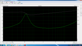
Attached is the measurement of the tweeter on axis at 50cm from the driver in box without filter, what kind of filter will you use? will be necessary notch or zobel filters?
TIA
Felipe
Attachments
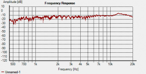
The peak at about 13kHZ will color the sound a bit, but the response is generally relatively flat. I would just use a high pass crossover filter on it and see what it sounds like before playing with EQ filters. You'd have to measure the impedance of the tweeter at 13kHZ, to know how to calculate the part values for a Zobal filter, if you wanted to deal with that.Hi Bob,
Attached is the measurement of the tweeter on axis at 50cm from the driver in box without filter, what kind of filter will you use? will be necessary notch or zobel filters?
TIA
Felipe
I take measurements above about 10kHZ with a grain of salt, since the wavelengths of the signal get so small that the slightest misalignment of the microphone to the tweeter can make a big difference in the measured result, plus not all "calibrated mics" are as accurate up there as they often lead you to believe (the Behringer mics for example).
Thanks, what kind of passive filter?
I guess 2nd order but I see some Seas kits with 3rd order....
I'm guessing that "Re" means DC resistance. That's diffderent than AC impedance at a certain frequency, which is what you need to measure. The inductance measurement isn't what you need for this either.I measured my drivers with my LCR:
Seas T25CF002
Re 4R8 & 4R9
Le 0.208mH & 0.373mH
SS 18W-8545-00
Re both 5R7
Le both 0.331mH
Yes Re is voice coil resistance, I measured the drivers following Elliot sound pages so function generator 10 ohms resistor & true RMS DVM.
Right tweeter
2k3-2k6Hz 0.009-0.008 volts AC
2k7-5k7 0.008-0.007
5k8-6k9 0.007-0.006
7k-25k 0.006-0.006
Right woofer
50-102Hz 0.017-0.014 VAC
102.5-119 0.015-0.014
120-141 0.014-0.012
142-169 0.013-0.011
170-799 0.012-0.012
800-2k1 0.013-0.014
Left tweeter
2k3-2k5 0.010-0.010
2k6-3k7 0.009-0.009
3k8-4k8 0.008-0.008
4k9-7k3 0.007-0.006
7k4-25k 0.006-0.006
Left woofer
50-58Hz 0.0018-0.0024
59-60 0.025-0.028
60-63 0.029-0.035
64-67 0.035-0.040
68-72 0.041-0.036
73-76 0.037-0.030
77-80 0.031-0.024
81-87 0.025-0.020
88-89 0.021-0.018
90-124 0.019-0.015
125-131 0.016-0.014
132-158 0.015-0.013
159-1k2 0.012-0.011
1k3-1k7 0.011-0.012
Last edited:
What are you trying to do?Please help.
Seas tweeter E0011-06 T25CF002
Tweeter rolls off at 11/12 (13KHz) as you can see from the FRD so that should not be a problem. (You can check the ZMA files also that follow below and match them with your driver)
http://www.rjbaudio.com/Audiofiles/FRD files/Seas T25-002.frd
http://www.rjbaudio.com/Audiofiles/FRD files/Seas T25-002.zma
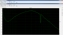
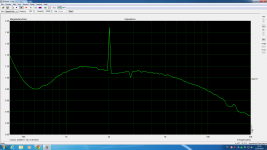
Limp measurements 110 ohms resistor
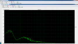
1st pic SS 18W-8545-00 left
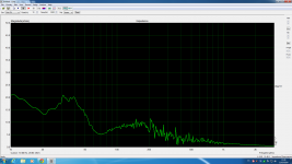
2nd pic SS 18W-8545-00 right
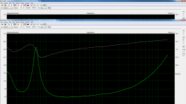
3rd pic Seas Millenium left
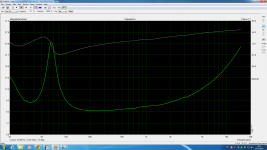
4th pic Seas Millenium right
1st pic SS 18W-8545-00 left
2nd pic SS 18W-8545-00 right
3rd pic Seas Millenium left
4th pic Seas Millenium right
Attachments
Attached new measurements, 1st pic SS-18W8545-00 left channel, 2nd pic SS-18W8545-00 right channel, 3rd pic Seas Millenium left channel and 4th pic Seas Millenium right channel. I guess now are OK")
Attachments

- Status
- This old topic is closed. If you want to reopen this topic, contact a moderator using the "Report Post" button.
- Home
- Loudspeakers
- Multi-Way
- Help for 3 or 4 way loudspeaker