Ok in tracking the buzz down I've...
- disconnected the SE output from the balanced/SE input transformer so no input. Still buzzes.
- checked so the grounding including the heaters for the indirectly heated 5842 and the 6x5gt indirectly heated rectifiers. All good and the heater voltages are balanced around 0v
- disconnected the 45 grid from the interstage (as it's fixed bias I took the bias directly there). Buzz gone. I conclude it's the 5842 because both the 45 and bias are still in play.
I've bypassed both of the filter caps with other caps, no change. I don't think it's in the PSU.
Time to rework the 5842 base I think
Last edited:
Do you have a scope?
You don't need to connect all 4 of the grid pins, this is really only relevant when the tube is being used for its intended purpose with a grounded grid connection.
I would use a single 1K (or larger) resistor right on the "lucky" grid pin.
I tend to use ferrite beads in cathode and plate leads, a 10 - 47 ohm resistor right at the plate may be helpful.
I will bypass the filament pins to chassis ground with 0.01uF disk ceramics in some cases if the filament supply is in another box.
Cathode right to ground?
Have you tried a different 5842?
I have had persistent buzz problems with an amplifier design using an IT coupled D3A driver, so I can relate. (The D3A oscillates and is modulated by what is yet to be determined)
Found the problem. I was missing a psu return wire in the 45. So focused on the 5842 I missed it.
I now have a quiet amp, but the output is lower than the left. I'll rework the 5842 to match - I put a 10r into the anode (surely can't be that) and the grids each have 23k on them (the left have 10k I think).
Nice to have gotten past that buzz though.
I now have a quiet amp, but the output is lower than the left. I'll rework the 5842 to match - I put a 10r into the anode (surely can't be that) and the grids each have 23k on them (the left have 10k I think).
Nice to have gotten past that buzz though.
Found the problem. I was missing a psu return wire in the 45. So focused on the 5842 I missed it.
I now have a quiet amp, but the output is lower than the left. I'll rework the 5842 to match - I put a 10r into the anode (surely can't be that) and the grids each have 23k on them (the left have 10k I think).
Nice to have gotten past that buzz though.
OK removed the 10R from the 5842 anode and changed the grid-stoppers to match the left amp (10k on each of 4 grids in a cone-of-silence arrangement).
Amp now matches the left for volume and the pair sound superb. Thanks for help and support.
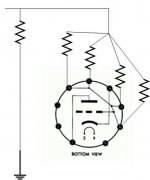
I have to confess to being slightly confused though. I had not expected the grid-stoppers to attenuate the input signal, because there's no current flowing through those resistors. Anyone help me understand ? Per the diagram the resistors are directly on the grid pins.
Attachments
Last edited:
I'm missing something. My 5842 / 45 amp uses a grid-stopper arrangement on the 5842 as per the diagram.
On my left amp (finished, working perfectly) I used 4x 12k, giving 3k overall. On my right amp I mistakenly used 4 x 22k, giving 5k5.
Once I'd finished troubleshooting the amp I put the pair together and noticed the imbalance. Once I realised the mistake, I corrected to match the left and hey presto they balanced.
But I don't understand why, which probably points at a key foundational mis-understanding of mine. Not surprising given I've self-taught over the past couple of years.
Could someone explain to me why those grid-stoppers attenuate the input signal ? I would expect with no current flowing there would be no voltage drop.
Attachments
 @RhythMick - please don't start multiple threads for the same/similar topic, which is against the Forum Rules. Your threads have been merged.
There is only a very small current through the grid stopper so very little attenuation. An exception is when a large value of grid stopper is used (e.g. many guitar amps); then treble gets attenuated due to Miller capacitance.
Yes thanks, with the help of the Valve Wizard site (fantastically helpful) I calculated the value of the stopper in conjunction with the Miller capacitance to help roll off the very high frequencies and avoid oscillation. The attenuation I saw though was across all frequencies and it matched the left when I changed the grid-stoppers to match.
Confused.
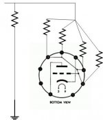
Thanks all. The grid to ground is in the right place. Top connects to the cone junction, while bottom goes to ground. The input connects across that grid to ground (see the diagram above).
Perfectly possible that the stopper value is higher than it needs to be. I'm still learning how to apply all the equations and the use of grid stop plus miller to roll off oscillation frequencies is definitely new for me. I'll experiment. 4 x 10k sounds superb.
Perfectly possible that the stopper value is higher than it needs to be. I'm still learning how to apply all the equations and the use of grid stop plus miller to roll off oscillation frequencies is definitely new for me. I'll experiment. 4 x 10k sounds superb.
How are you biasing the 5842? Although your grid stoppers seem a bit high in value (and I don't believe you actually need them on all 4 grid pins) you would only get attenuation if there is significant grid current; if so, you would also be getting some distortion from this. Now, as the 5842 was designed for grounded-grid operation it is possible that the datasheet recommended bias does not worry about grid current because in the usual circuit there would be no significant grid circuit impedance to cause problems.
A datasheet I found suggests that under those conditions the grid current should be less than 0.5uA. This is still high by normal standards, but should not cause significant attenuation. Maybe your valves are out of spec?
Another possibility is that by having four grid stoppers in parallel you have added so much stray capacitance that the stopper is ineffective and the valve is singing at some UHF frequency. Unlikely, but this valve was designed to amplifiy at very high frequencies and it doesn't know that you want it to stop at a few 10's of kHz.
Another possibility is that by having four grid stoppers in parallel you have added so much stray capacitance that the stopper is ineffective and the valve is singing at some UHF frequency. Unlikely, but this valve was designed to amplifiy at very high frequencies and it doesn't know that you want it to stop at a few 10's of kHz.
- Status
- This old topic is closed. If you want to reopen this topic, contact a moderator using the "Report Post" button.
- Home
- Amplifiers
- Tubes / Valves
- Help diagnosing weird noise