OK Here we go. This is the best I've been able to come up with.
One caveat. I'm not really sure what I should have used for Z offset when modelling. I ended up going with -30mm on the woofer. This is the theoretical difference between the accoustic centre of the tweeter and the accoustic centre of the mid. The only way to determine it in reality is with proper measurements. Hopefully 30mm is near enough.
I simmed this in speaker workshop. I went with a variation on Steve's low pass from post 15 and a fairly standard 3rd order electrical for the high pass (with padding).
getting good phase matching was VERY difficult. I really appreciate how much easier it is when you time align the drivers now!
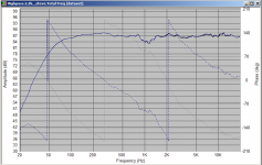
The crossover is 4th order accoustic Bessel at 2.2Khz (sort of). In reality it is a 2.2Khz 4th order bessel on the tweeter and a 2.6Khz Linkwitz riley on the woofer. That's just what worked to give me decent phase through the crossover region and a flatish response.
Without real measurements of the drivers I wouldn't try and spend more time optimising this as it could well be wrong due to not knowing for certain the Z offset.
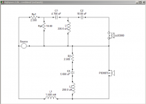
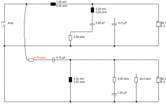
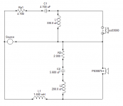
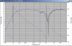
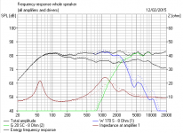
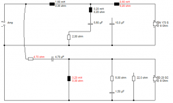
Anyway attached is the schematic of the crossover, and the various frequency response plots.
Tristan maybe it would be a good idea to see what Steve thinks before considering implementing this.
Coils DCR values are: (all from standard Jantzen air cores, the 1.5mH you could get a p-core for cheaper with a lower DCR without detriment).
330uH 0.26 ohms
200uH 0.193 ohms
1.5mH 0.3 ohms
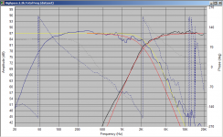
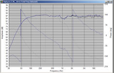
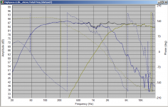
The third pic shows the individual responses. red curves are the 4th order bessel target. Yellow (green? I'm colourblind) is the 2.6Khz LR target.
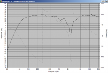
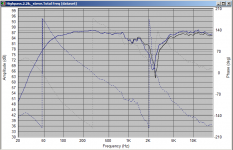
4th shows the reverse null FR (not fantastic but not awful either, but as mentioned without acurately knowing the Z offset a bit meaningless).
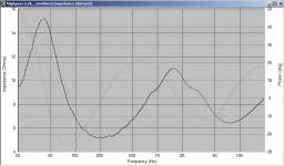
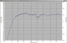
5th shows the impedance plot of the final speaker.
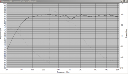
edit: the dip around 1Khz is inherent in the midbass and very difficult to do anything about. Other than that I think that the response is pretty flat!
edit2: 2.2Khz is IMO a pretty low crossover point but looking at the specs of the SS I think it should be ok, especially with a 4th order slope.
Tony.
One caveat. I'm not really sure what I should have used for Z offset when modelling. I ended up going with -30mm on the woofer. This is the theoretical difference between the accoustic centre of the tweeter and the accoustic centre of the mid. The only way to determine it in reality is with proper measurements. Hopefully 30mm is near enough.
I simmed this in speaker workshop. I went with a variation on Steve's low pass from post 15 and a fairly standard 3rd order electrical for the high pass (with padding).
getting good phase matching was VERY difficult. I really appreciate how much easier it is when you time align the drivers now!
The crossover is 4th order accoustic Bessel at 2.2Khz (sort of). In reality it is a 2.2Khz 4th order bessel on the tweeter and a 2.6Khz Linkwitz riley on the woofer. That's just what worked to give me decent phase through the crossover region and a flatish response.
Without real measurements of the drivers I wouldn't try and spend more time optimising this as it could well be wrong due to not knowing for certain the Z offset.
Anyway attached is the schematic of the crossover, and the various frequency response plots.
Tristan maybe it would be a good idea to see what Steve thinks before considering implementing this.
Coils DCR values are: (all from standard Jantzen air cores, the 1.5mH you could get a p-core for cheaper with a lower DCR without detriment).
330uH 0.26 ohms
200uH 0.193 ohms
1.5mH 0.3 ohms
The third pic shows the individual responses. red curves are the 4th order bessel target. Yellow (green? I'm colourblind) is the 2.6Khz LR target.
4th shows the reverse null FR (not fantastic but not awful either, but as mentioned without acurately knowing the Z offset a bit meaningless).
5th shows the impedance plot of the final speaker.
edit: the dip around 1Khz is inherent in the midbass and very difficult to do anything about. Other than that I think that the response is pretty flat!
edit2: 2.2Khz is IMO a pretty low crossover point but looking at the specs of the SS I think it should be ok, especially with a 4th order slope.
Tony.
Attachments
Last edited:
I've had a bit of a snuffle this week too. Cold weather, eh! 
This is all coming along nicely now, IMO. You get what you get with 6" paper drivers. The LCR seems to work nicely, better than a simple 10uF shunt, and I trust Tony's estimate of where the notch goes. What? About 4.5kHz. I've built this sort of circuit, and it sounds OK.
We can only guess with the acoustic centres and phase alignment, but the D2905-9300 is a known quantity.
https://www.madisoundspeakerstore.com/scanspeak-soft-dome-tweeters/scanspeak-classic-d2905/9500-1-tweeter-textile-dome/
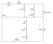
A highish 18uF is saying second order tweeter to me. So let's lose it altogether. This is a LR4 at heart. The lean midrange and power dip at crossover. I've tidied your tweeter attenuation there, Tony. You must have been tired. Tweeter level is always select on test IME. The red component.
You can use a Zobel or a simple 22R for tweeter tonality. The 22R will be brighter at the very top. So here's one way of doing it. Nice and simple. Phase is good too.
This is all coming along nicely now, IMO. You get what you get with 6" paper drivers. The LCR seems to work nicely, better than a simple 10uF shunt, and I trust Tony's estimate of where the notch goes. What? About 4.5kHz. I've built this sort of circuit, and it sounds OK.
We can only guess with the acoustic centres and phase alignment, but the D2905-9300 is a known quantity.
https://www.madisoundspeakerstore.com/scanspeak-soft-dome-tweeters/scanspeak-classic-d2905/9500-1-tweeter-textile-dome/
A highish 18uF is saying second order tweeter to me. So let's lose it altogether. This is a LR4 at heart. The lean midrange and power dip at crossover. I've tidied your tweeter attenuation there, Tony. You must have been tired. Tweeter level is always select on test IME. The red component.
You can use a Zobel or a simple 22R for tweeter tonality. The 22R will be brighter at the very top. So here's one way of doing it. Nice and simple. Phase is good too.
Attachments
The two ohms rather than 2.5 ohms is intentional, it is an improvement
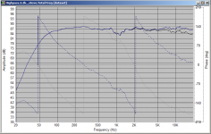
I thought that the 18uF was helping with the phase but apparently it wasn't! Yes I was tired!! Attached the sims with Steve's enhancements. Thanks Steve! I'd reached a point where I had had enough
edit blue is the original, Black is Steve's enhanced version (less is more). Tweeters are a very personal thing, I suspect the slighly lower level will be a good thing but if it sounds a bit too laid back, reducing the 4.7 a bit will bring the level up. 4th pic shows the comparison with 3.6K instead of 4.7K.
edit2: Just realised I didn't put in the tweeter zobel, will do that and see what it does, never used one myself. Oh and also dropped the tweeter coil to 300uH which has a big improvement on the reverse null. Need my morning coffee!!
Tony.
I thought that the 18uF was helping with the phase but apparently it wasn't! Yes I was tired!!
Attached the sims with Steve's enhancements. Thanks Steve! I'd reached a point where I had had enough edit blue is the original, Black is Steve's enhanced version (less is more). Tweeters are a very personal thing, I suspect the slighly lower level will be a good thing but if it sounds a bit too laid back, reducing the 4.7 a bit will bring the level up. 4th pic shows the comparison with 3.6K instead of 4.7K.
edit2: Just realised I didn't put in the tweeter zobel, will do that and see what it does, never used one myself. Oh and also dropped the tweeter coil to 300uH which has a big improvement on the reverse null. Need my morning coffee!!
Tony.
Attachments
Last edited:
OK with the 300uH instead of 330uH you can see the reverse null is much better, there is a very small difference in normal polarity but not great.
Second pic shows the effect of the zobel. So this will be down to taste.
Interestingly getting the really good reverse null means only a very small overlap at the crossover frequency, I was aiming for reasonable phase tracking either side of the crossover frequency as well. What difference this makes I'm not sure.
Tony.
Attachments
Great news Tristan! Before you buy a PC you might want to have a look at boxsim Downloads it may run ok on your winxp vm. I think it is what Steve uses, and it looks very good. I will have to download a copy myself to have a play with!
I've also learnt something as well, I made the same mistake with the lpad with my MTM's that Steve pointed out earlier I need to change my crossover as a result.
Tony.
Before you buy a PC you might want to have a look at boxsim Downloads it may run ok on your winxp vm. I think it is what Steve uses, and it looks very good. I will have to download a copy myself to have a play with! I've also learnt something as well, I made the same mistake with the lpad with my MTM's that Steve pointed out earlier I need to change my crossover as a result.
Tony.
Everyday is a school day
Really pleased with the results so far and this is just with cheap bits I had kicking about. I'm planning on building the final iteration in the next few weeks. I'm going to replace the ferrite cored inductors with jantzen aircores. What spec should I be looking at? I'm confused about wire thickness etc. Also any recommendations re capacitors? I don't want to spend silly money, but would like something decent.
Really pleased with the results so far and this is just with cheap bits I had kicking about. I'm planning on building the final iteration in the next few weeks. I'm going to replace the ferrite cored inductors with jantzen aircores. What spec should I be looking at? I'm confused about wire thickness etc. Also any recommendations re capacitors? I don't want to spend silly money, but would like something decent.
Hi Tristan, these are the specific coils I used the data for in the sim.
1.5mH Air-Core 1.5mH 14AWG
300uH Air-Core 0.3mH 18AWG
200uH Air-Core 0.2mH 18AWG
I would try to stick with the same DCR for the 300 and 200 uH coils, as changes to the DCR on these will have more of an effect than on the big one.
The 1.5mH you could also opt for a p-core (note I haven't used these) but for your application I don't think there would be any risk of saturation (the thing you want to avoid with cored inductors). P-Core 1.5mH 14AWG
This should give you a tiny little bit more spl in the bass region (around 0.3db) based on the sim. It will probably be a little more complex that that in reality as with a reflex enclosure the series resistance in series with the driver also affects the tuning, but it's only going to make a tiny difference.
I'd say it comes down to cost. The 14Gauge air cores are not so cheap! If cost is an object then these would be the best option P-Core 1.5mH 18AWG Still lower DCR than the air core and less than 1/3rd the cost!
The attachment shows with the 0.3ohm air core in blue, and with the 0.1ohm Pcore in black. Not much difference!
On capacitors, I used Axon's which I got from parts connexion they are good qualtity and probably best bang for buck out there, but they don't seem to have the range of values they used to.
As they are only small caps though you might want to go for something a little more up market (I'm not into boutique caps), I've seen plenty of people recommend the mundorf M-Caps (MKP series). Or perhaps the Jantzen standard Z caps. The jantzen superior Z caps are in a different league price wize!! but get rated much more highly in the humble homemade hifi subjective capacitor tests. I decided I was happy with the sound of my axon's and not to worry about spending any more money! I bought them originally to test out the crossover without spending big bucks and never felt the need to get something more expensive.
Tony.
Attachments
I'm impressed that you are actually getting on with this, tristan! Tweeter level is incredibly sensitive IMO. And boomy bass definitely intrudes. This is tweakable.
I think I gave you a link to Wilmslow and Maplin for bits:
Bits & Pieces
5 Way Tagstrip | Maplin
Baked aircore coils are probably ideal, and you might try Audio Inductors 0.01mH - 10.00mH, Ferrite, Air Cores, Iron Dust.. This sticks the windings together, so will be better than loosely wound coils which might rattle. Resistance is not a big issue really, that's just tonal. Ferrite may not be as bad as people think, because speakers are usually ferrite magnets anyway, so any improvement is marginal. I can never hear any difference with boutique caps or resistors myself.
It's a cost and size decision really. Interestingly, Alan Shaw of Harbeth breaks the rules a lot, and he knows what he is doing! He finds polyester caps and ferrites on tweeters good enough. Note the right angle placement of coils to avoid interaction.
Not many people seem to know this, but you can unwind coils to reduce values, then scrape off a little of the insulating enamel for a good solder. Since inductance is the square of the number of turns, you take off less than you might think. I check with a good meter anyway.
Attachments
Thanks Steve I did actually reduce to inductors I had from .5mh to .3mh yesterday, so was aware of this. They're actually the ones you posted a link to! I've priced up a a load of Jantzen bits at wilmslow and they come out about £60 for each XO. Seeing as the cabinets were only £25 I have no concern spending that much. The tweeters I pinched from my Nuneutrons and the mid/woofers were £95 so total cost is very low
I did actually reduce to inductors I had from .5mh to .3mh yesterday, so was aware of this. They're actually the ones you posted a link to! I've priced up a a load of Jantzen bits at wilmslow and they come out about £60 for each XO. Seeing as the cabinets were only £25 I have no concern spending that much. The tweeters I pinched from my Nuneutrons and the mid/woofers were £95 so total cost is very low Fantastic project really. True DIY! Some pictures would be nice.
FWIW, you get a feel for what does what in a filter after a bit of modelling.
Downloads
What looks like a second order bass filter is really a third order when you include voice-coil inductance. Here's how you would take down the midrange a little, for instance.
FWIW, you get a feel for what does what in a filter after a bit of modelling.
Downloads
What looks like a second order bass filter is really a third order when you include voice-coil inductance. Here's how you would take down the midrange a little, for instance.
Attachments


VERY NICE!
Oh, wait. You mean you are doing a second one?
This 104mm SEAS 27TBFC/G tweeter looks very Harbeth:
H1212-06 27TBFC/G
Different Zobel, maybe 7.5R and 0.68uF. But doable I think. Different sound altogether.
Oh, wait. You mean you are doing a second one?
This 104mm SEAS 27TBFC/G tweeter looks very Harbeth:
H1212-06 27TBFC/G
Different Zobel, maybe 7.5R and 0.68uF. But doable I think. Different sound altogether.
- Status
- This old topic is closed. If you want to reopen this topic, contact a moderator using the "Report Post" button.
- Home
- Loudspeakers
- Multi-Way
- Help designing a crossover for AVI Duo (sort of)