Hi guys
I have built few psu from PCB. but this is my first psu build from scratch using point to point wiring.
i need help to debug the psu i am building now. its using the BC546B for positive supply and BC 556B for negative part
power transformer is 30VAC CT 1A
problem is:
negative supply give out the expected regulated voltage while positive part dont
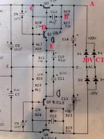
below attached the schematic and left part of the picture is output. i also add bypass cap WiMA MKP 0.1uF to the C14, C15 = 2200uF 50v
details on the mark in schematic, measurement is taken from the ground point (middle of the schematic) to the mark position:
for negative part which perform as expected:
A=-21.3VDC
B=-18.1VDC
C=-14.2VDC
D=-14.7VDC
E=-1.6VDC
while positive part which do not perform as expected:
A=20.7VDC
B=15.4VDC
C=10VDC
D=10.6VDC
E=1.5VDC
what i have tried so far that do not fix the problem:
1. change the BC546B with new pair
2. resolder every points
3. recheck all the components with DMM and capacitor tester which all perform well
what might be the problem? leaking electrolytic? but all the components are new.
thanks in advance for all the inputs
I have built few psu from PCB. but this is my first psu build from scratch using point to point wiring.
i need help to debug the psu i am building now. its using the BC546B for positive supply and BC 556B for negative part
power transformer is 30VAC CT 1A
problem is:
negative supply give out the expected regulated voltage while positive part dont
below attached the schematic and left part of the picture is output. i also add bypass cap WiMA MKP 0.1uF to the C14, C15 = 2200uF 50v
details on the mark in schematic, measurement is taken from the ground point (middle of the schematic) to the mark position:
for negative part which perform as expected:
A=-21.3VDC
B=-18.1VDC
C=-14.2VDC
D=-14.7VDC
E=-1.6VDC
while positive part which do not perform as expected:
A=20.7VDC
B=15.4VDC
C=10VDC
D=10.6VDC
E=1.5VDC
what i have tried so far that do not fix the problem:
1. change the BC546B with new pair
2. resolder every points
3. recheck all the components with DMM and capacitor tester which all perform well
what might be the problem? leaking electrolytic? but all the components are new.
thanks in advance for all the inputs
Attachments
Not really sure how that topology would work very well. I don't see a reference. A typical "regulated" supply takes a sample of the output voltage and compares it to a fixed reference. The difference is (ideally) amplified and applied to the pass element for correct reaction.
Offhand, though, it looks like the base of the pass transistor is starved for current. R27 and R29 may be too high in resistance, depending on how much current you require.
Offhand, though, it looks like the base of the pass transistor is starved for current. R27 and R29 may be too high in resistance, depending on how much current you require.
i am not sure bout this topology as well. i have build this exact psu but its on pcb. hence when i build it point to point wiring with better components (original pcb cant fit a wirewound resistors and some big MKP) then i encounter above problems.
would this be the case that i wire the BC546B incorrectly? thx
would this be the case that i wire the BC546B incorrectly? thx
Okay, well, I will stick to my original statement then.
Base current to drive the pass transistor (not sure what part # it is) comes from R29 and R27, at a whopping 30 kohm.
Let's assume beta of this pass transistor is 100, which is pretty high unless you're running a darlington. At 150 mA output current, your base drive requirement is 1.5mA. Good so far?
Therefore, this 1.5 mA is derived from the 30k resistor. 1.5m * 30k = 45V. You don't have 45V to spare; you only have about 5V. Therefore, you are starving the pass transistor.
Reduce the values of R29 and R27, depending on the minimum beta of the pass transistor.
i agree with zig. there should have a reference. a zener in place of the error amp emitter resistor would be one way to do it.
without a reference, the output will tend to float with the load. what you really have here is closer to a capacitance multiplier. it will improve the filtering, but not really regulate.
without a reference, the output will tend to float with the load. what you really have here is closer to a capacitance multiplier. it will improve the filtering, but not really regulate.
Hi zigzagflux,
it uses BC546B for positive regulation and BC556B for negative regulation.
i try R29=2K3 it bring up the voltage abit. but the voltage different between point B and C is around 6V.
while as the reference, the voltage different at negative side between B and C is only 2V
i just recheck again all the capacitor and they are good.
Don't bother checking any of your capacitors, they are not suspects.
The BC546B has a current gain around 200, but this is typical. I would suggest 100. Base drive requirement is 150/100 = 1.5 mA.
You get about 5V to work with, so 5/1.5 mA = 3.3K MAXIMUM. This is for R27 and R29 together, so I would suggest maybe 1.5K each.
This does not preclude my belief that your circuit still will not work very well, since there is no reference. May I suggest the following simplistic ideas?
http://www.electronicsinfoline.com/...d_Battery/Variable_Regulated_Supply/7168.html
hi zigzagflux.
thanks for the suggestion. i will try the 1.5K.
i am just wondering, why the negative part perform as intended while the positive part not?
if we starved the BC546B, arent the BC556B also starved as well?
as for your suggestion. do you have the complete schematic that i can try to build?
i am after a clean power supply to power a dac. which topology do you recommend? thx in adv
milen007 said:i am just wondering, why the negative part perform as intended while the positive part not?
if we starved the BC546B, arent the BC556B also starved as well?
That's a good question. Best answer I have is that you got lucky matching headroom, current availability, beta, and load requirements.
as for your suggestion. do you have the complete schematic that i can try to build?
i am after a clean power supply to power a dac. which topology do you recommend? thx in adv
I will look up at home what I think is one of the best series regulators out there. You could possibly improve on it by going with a shunt regulator (some claim superior performance with DACs), but I'll leave that up to someone else's design. The circuit will really be appropriate only for printed circuit board, though; it uses monolithic transistors and opamps.
IMO, the circuit you have provided is unsuitable for a quality DAC supply.
Here is essentially the same design, though the series regulator is a little different. Look at Figure 13. Values will have to be adjusted to suit your specific needs.
If you are very new at design, though, it may be better to start off with a simpler topology. It's just nice to use a good regulator for a DAC.
http://www.intersil.com/data/fn/fn817.pdf
If you are very new at design, though, it may be better to start off with a simpler topology. It's just nice to use a good regulator for a DAC.
http://www.intersil.com/data/fn/fn817.pdf
- Status
- This old topic is closed. If you want to reopen this topic, contact a moderator using the "Report Post" button.
- Home
- Design & Build
- Parts
- help debug regulated psu