So, not really an elaborated circuit and yet I made it simpler, omitted the pre-amp and built a single channel, perhaps I'll add the second later.
Basically it lacks power, I reckon 1 watt, and sounds terrible.
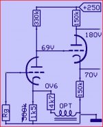
Because I'm building one channel I adjusted the 500 ohm resistor to give around 270 volts +B1.
I was concerned about the split phase inverter voltages, so fiddling with the +B2 voltage and 150k resistors I endup with matching about 108v per phase using 470k resistors at plate and cathode and increasing the 5k resistor until I got around 180v +B2. Still didn't work.
I'm using all new valves and replaced all of them several times.
Replaced the purpose built transformer by generic pp EL84 OT's. No luck
Any ideas? I don't have a scope, just analog and digital multimeters.
Is there anything in particular I should focus while dealing with this ? I don't think there are problems with the 6C5 or first 12ax7 triode. Tone controls work fine.
Basically it lacks power, I reckon 1 watt, and sounds terrible.
Because I'm building one channel I adjusted the 500 ohm resistor to give around 270 volts +B1.
I was concerned about the split phase inverter voltages, so fiddling with the +B2 voltage and 150k resistors I endup with matching about 108v per phase using 470k resistors at plate and cathode and increasing the 5k resistor until I got around 180v +B2. Still didn't work.
I'm using all new valves and replaced all of them several times.
Replaced the purpose built transformer by generic pp EL84 OT's. No luck
Any ideas? I don't have a scope, just analog and digital multimeters.
Is there anything in particular I should focus while dealing with this ? I don't think there are problems with the 6C5 or first 12ax7 triode. Tone controls work fine.
An externally hosted image should be here but it was not working when we last tested it.
Providing measurements as asked by DF96 is indeed the first step.
For the phase splitter it is good to roughly split the available B+ in 3: 1/3 across the tube, 1/3 across cathode R and 1/3 across anode R. That means the grid of the phase splitting tube is sitting at about 1/3 of B+. As the grid is connected to the plate of the driver tube, this one should also be at 1/3 of B+, or 80V.
Alternatives are to AC couple driver and the auto biased phase splitter, to build in a step network, use a tube that works better at lower B+ (what MJ did in his Bevois Valley, 3rd edition of Valve Amplifiers, employing a ECC88/E88CC) or employ a (separate) B+ for the driver (this is what SY did in his red light district, using about 350V - 400V and an ECC81).
but lets start with the measured values")
For the phase splitter it is good to roughly split the available B+ in 3: 1/3 across the tube, 1/3 across cathode R and 1/3 across anode R. That means the grid of the phase splitting tube is sitting at about 1/3 of B+. As the grid is connected to the plate of the driver tube, this one should also be at 1/3 of B+, or 80V.
Alternatives are to AC couple driver and the auto biased phase splitter, to build in a step network, use a tube that works better at lower B+ (what MJ did in his Bevois Valley, 3rd edition of Valve Amplifiers, employing a ECC88/E88CC) or employ a (separate) B+ for the driver (this is what SY did in his red light district, using about 350V - 400V and an ECC81).
but lets start with the measured values
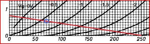
The first sentence is only true at a particular anode current - anode resistance varies strongly with anode current.kuroguy said:12ax7 plate resistance at 250 volts is 62.5K. change your phase splitter resistors from 150K to 62.5K.
The second sentence certainly does not follow from the first sentence - as a general rule the load resistors should be greater than the anode resistance. You may be confusing DC resistance (V/I) with AC or slope resistance (dV/dI).
470k resistors at plate and cathode
Isn't a bit high? If schematic shows 150k i will follow the schematic ...
Isn't a bit high? If schematic shows 150k i will follow the schematic ...
Yes 470k was a nonsense test.
Replaced the 150k resistors by 33k , now I've got 162.5 at plate and 82.5 between plate and cathode, there's a slight improvement.
Also I measured the screen grid current and it's about 40mA per tube !!! wth is going on.,

You probably didn't measure the screen grid current. 40mA would destroy the screen grid quite quickly.
For sure !
When will you stop doing stupid things and put in the 1k5 I sugested ?Yes 470k was a nonsense test.
Replaced the 150k resistors by 33k , now I've got 162.5 at plate and 82.5 between plate and cathode, there's a slight improvement.
Also I measured the screen grid current and it's about 40mA per tube !!! wth is going on.,
Mona
I think, this schematic isn't suitable for combination of 12AX7 and 6AQ5....12AX7 works with +U more than 300v and 6AQ5 works with about 250-300 v and Your PS doesn't provide +U for normal modes of both tubes.
IMO, You have two ways to follow... 1- change 12AX7 to ECC85 or 88.....or 2- change 6AQ5 to 6BQ5, decrease power resistors before +B1 and +B2 to about 50-100 ohm to increase both +U for better modes of 6AQ5 and 12AX7....for better sounding You can change 12AX7 to 12AT7, IMO....I'd like advise You second way....
In both cases, note please, You must adjust modes of two triodes for provide direct theirs coupling, that isn't easy. /Why You don't use another similar schematic? I don't like this/.
Last edited:
The second 12ax7 (Concertina Splitter) should have 1/2 B+ across it and each resistor should have about 1/4 B+ for maximum signal amplitude to occur.
You have to adjust the bias point on the first 12ax7 to about 65 volts at the plate as it is direct coupled. You can change the value of the 500k anode resistor to achieve this bias.
You have to adjust the bias point on the first 12ax7 to about 65 volts at the plate as it is direct coupled. You can change the value of the 500k anode resistor to achieve this bias.
These direct coupled drivers have been done for decades, but they're touchy and compromise both stages' DC conditions. I understand the desire to keep things "simple", but until you have a B+ of almost 400 volts it makes for an input stage with serious possible grid current nonlinearities.
Separating the stages with a coupling cap is something to consider when available B+ is only 250 volts. Battery coupling is another option for consideration. Or, some folks use a resistive divider with the first R bypassed with a cap.
All good fortune,
Chris
Separating the stages with a coupling cap is something to consider when available B+ is only 250 volts. Battery coupling is another option for consideration. Or, some folks use a resistive divider with the first R bypassed with a cap.
All good fortune,
Chris
- Status
- This old topic is closed. If you want to reopen this topic, contact a moderator using the "Report Post" button.
- Home
- Amplifiers
- Tubes / Valves
- Help 6AQ5 pushpull