Kari,
I used the LM1010 voltage reference. I tried it with and without a 47uF cap in parallel, and it didn't seem to make any real difference.
In retrospect to my circuit, you could use a single voltage reference for both cascode transistors instead of the double arrangement I used. Another option for the voltage reference is to use a simple pair of resistors as a voltage divider between the V+ and GND.
Cheers, Terry
Wiki again; Room for bypass capacitors
Sorry, Kari,
But could you tell me exactly how to get into the Wiki? I have clicked the link in this thread and also clicked the diyAudio.com Logo at the top of this thread, then clicked "Wiki" (adjacent to ""Forums") and I am getting a "Page not available" message.
In the meantime, I will try on a friends computer, which may work.
Although I have not done this myself as yet, others have said that putting in small bypass film capacitors adjacent to larger value electrolytics gives a noticable improvement in sound in may Pass labs projects. Is there room to do this on your boards? It looks like there should be, but your opinion is valuable.
Regards,
George.
Re: Wiki again; Room for bypass capacitors
Actually there is just such an article in the May issue of AudioXpress covering the merits or drawbacks of bypassing Electrolytics.
Regards
Anthony
GeorgeBoles said:Sorry, Kari,
But could you tell me exactly how to get into the Wiki? I have clicked the link in this thread and also clicked the diyAudio.com Logo at the top of this thread, then clicked "Wiki" (adjacent to ""Forums") and I am getting a "Page not available" message.
In the meantime, I will try on a friends computer, which may work.
Although I have not done this myself as yet, others have said that putting in small bypass film capacitors adjacent to larger value electrolytics gives a noticable improvement in sound in may Pass labs projects. Is there room to do this on your boards? It looks like there should be, but your opinion is valuable.
Regards,
George.
Actually there is just such an article in the May issue of AudioXpress covering the merits or drawbacks of bypassing Electrolytics.
Regards
Anthony
Re: Wiki again; Room for bypass capacitors
Try this link: http://www.diyaudio.com/wiki/
As for the preamp board itself it would not be advisable to use elcos. Use some filmcaps instead. As for the powersupply the elcos are bypassed with filmcaps.
/Kari
GeorgeBoles said:Sorry, Kari,
But could you tell me exactly how to get into the Wiki? I have clicked the link in this thread and also clicked the diyAudio.com Logo at the top of this thread, then clicked "Wiki" (adjacent to ""Forums") and I am getting a "Page not available" message.
In the meantime, I will try on a friends computer, which may work.
Although I have not done this myself as yet, others have said that putting in small bypass film capacitors adjacent to larger value electrolytics gives a noticable improvement in sound in may Pass labs projects. Is there room to do this on your boards? It looks like there should be, but your opinion is valuable.
Regards,
George.
Try this link: http://www.diyaudio.com/wiki/
As for the preamp board itself it would not be advisable to use elcos. Use some filmcaps instead. As for the powersupply the elcos are bypassed with filmcaps.
/Kari

Schematics/ Parts
Are there schematics for the power supply and L/R boards?
Is there a parts list anywhere?
I'd like to order some parts as soon as I pay for the board, which looks like it will be in a few days. It would be good to have schematics and a parts list at least to ensure that I can order appropriate parts that will fit the boards.
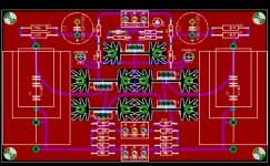
Here's a pic of the boz pcb. I just need to process it in CAM350 for a final check and add the last text to the silkscreen.
BOM:
R1,R2,R6,R7: 1,5k 3W
R3,R4: 22
R5,R9,R12,R13: 221
R8: 27
R10,R11: 50k
R14,R15: 10k
R16,R17,R20,R21: 100k
R19,R18: 39k
Q1,Q2,Q3,Q4,Q5: IRF610
REF1,REF2: LM4040-10 or any other 10V voltagereference
C1: 22uF
C2,C3: 1000uF/100V
C4,C5: any polyprop cap between 4,7-30uF, pick what't you think is best
D1: 1N5235B
If you choose not to cascode you can omit R10,R11,REF1,REF2,Q2,Q3. You also need to short Q2,Q3 D and S.
/Kari
Attachments
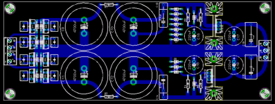
And here's the pwr pcb.
BOM:
D1,D2,D3,D4,D5,D6,D7,D8: Choose whatever you think is best. There is room for ex. 1N4004 and also for TO220 diodes.
C1,C2,C3,C4,C5,C6,C7,C8: Snubber caps, rm 5mm, you can leave these out. Here you could use for ex. 100n caps.
C9,C10,C11,C12: 4700uF/100V snapin type, also here you can choose some other value, as this is snapin type almost any value can be used.
C13,C14: 0,1uF, rm10mm or 15mm pitch
C15,C16,C17,C18: 220uF/100V
C19,C20: 1uF, 15mm pitch
R1,R2: 27/2W
R3,R4: 1,5k
R5,R6: 221
Z1-Z7: 9.1V Zener
Z8-Z10: ~4,5V Zener (Choose so the total would be ~14V
Q1: IRF9610
Q2: IRF610
/Kari
Attachments
And boy, I like that picHere's a pic of the boz pcb
 Cant wait to see how it looks with those big fat 30uF polyprops on it, and loads of big Fischer heatsinks. That is one cool preamp
 Steen.
Re: volume
Actually the BOSOZ design does not have any pots in it. The potentiometer on the front end and back end are input and output attenuators and are not part of the circuit per se. The Potentiometer at the P5 is an averall gain adjustment that can be replaced with a jumper and changing the fixed vale of R15 which is in series with P5 and fixed at 150R. I found that a 430R resistor works bext here for about 12dB gain, just like NP suggested in the orignal design.
For a volume contol a 5K stereo stepped ladder attenuator on the output is best and is what I will use in Kari's design.
Regards
Anthony
lgreen said:I hate to be a pain but...uh.... where's the vol control go? My bosoz has like 5 pots in it, and this one doesn't appear to have any.
Actually the BOSOZ design does not have any pots in it. The potentiometer on the front end and back end are input and output attenuators and are not part of the circuit per se. The Potentiometer at the P5 is an averall gain adjustment that can be replaced with a jumper and changing the fixed vale of R15 which is in series with P5 and fixed at 150R. I found that a 430R resistor works bext here for about 12dB gain, just like NP suggested in the orignal design.
For a volume contol a 5K stereo stepped ladder attenuator on the output is best and is what I will use in Kari's design.
Regards
Anthony
Coulomb said:Hello Kari, when are you going to start collecting the funds?
Anthony
ASAP, i just found out that i cannot extract the email adds from diyaudio.com so i'll send the invoices manually trough diyaudio.com instead.
/Kari
- Status
- This old topic is closed. If you want to reopen this topic, contact a moderator using the "Report Post" button.
- Home
- Amplifiers
- Pass Labs
- Heatsinks for Bosoz?