Hi AndrewT.
I don't understand the term "soak-test". English is (as you can tell) not my native language.
I have done a lot of measurements on airspeed, temperature and so on. Theese all indicate that my sims are spot on.
But I cant measure the die-temp directly so I'll have to absolutely sure about all assumptions.
I would like to use more heatsinks, but I haven't got the space.
Regards TroelsM
TroelsM said:Hi Poobah.
That's clever! I hadn't thought about using the on-resistance as a measure of the temperature. Nice!
About the "big chief" profile: I see your point about using aluminium as a spring, but the alu will "spring" more than a normal mounting and as far as I can see it works great in real life.
My only worry is that I'll be doing a design that takes about 800 fets in all, and I don't know how I'll get the "assembly-crew" to put the fet in the clip the right way....
Regards TroelsM
For fets, you can also use the body diode.
Build a constant power circuit with 10 or 20 volts drain, 1 amp or so conduction via gate control, giving you controlled power.
Build a timing circuit, have it turn the gate drive off for 100 or 200 uSec at the same time as the drain supply is turned off.
Use a constant current 10 milliamp source to pull the drain negative, this turns on the body diode.
Gate a s/h to look at this diode voltage within 10 uSec of the turn off.
Rep rate can be 200 to 500 milliseconds.
If you first characterize the body diode, you can use it's voltage to provide feedback to the control power level, allowing you to dial directly the desired junction temperature, and reading the power level that produces it.
I did this back when dino's ruled the earth. It is really neat pushing 100 amps into an assembly, then detaching them from the heatsink and watching the power drop, keeping constant junction.
Best and most accurate method i've ever used.
Cheers, John
Oh, btw. If you run an adjustable gating, you can delay the s/h out in time and check all the thermal interfaces..die to copper, copper to sink.
Communication, in theory, is the transferral if information that was not previously known.. This, I already knew..poobah said:John... you're nuts bud... really. -
poobah said:You used to work for IR didn't you?
They wish..
Honestly, they are very good with this thermal stuff. I do not recall if they published any rudimentary circuits to do what I posted, the book I have doesn't have it.
Back in the day..I think it was 91 or 92, I designed the test setup I described. Luckily, I had a really good tech, so he was able to take the block diagram and put good circuitry together. It was in support of military product, and I was doin thermal analysis, thermal design, encapsulation of the assemblies, and thermal testing both for design verification as well as production screening.
AndrewT said:Hi,
I'm just wondering what resources, both human and hardware, one needs to support the design and building of that test setup?
And then what does one do with the results?
If anybody is interested, I can provide details. I have the basic design in a notebook here. I could post a detailed block diagram with relevant theory, and the members could have fun designing the active circuitry.
You need a supply to drive the dut to sufficient power. You need some pass silicon, a s/h chip, some op amps.
Use is very easy..
1. Measure the TDP (temp dependent parameter) at several temperatures, using the equip with the power diss disabled. This normally gives a rather straight line vs temp.
2. Mount the dut.
3. Dial in the desired junction TDP. This is a reference signal the the machine makes the dut do.
4. Enable operation. When the junction is at the correct temperature, the machine will go into constant drive current mode. Multiply the measured voltage across the dut with the measured drive current, you have the power.
5. Measure the sink temp, your done.
If anyone is interested, we could build one on forum..
Cheers, John
ps..sorry, forgot results.
Using this tester, one can determine the thermal enviro one needs to produce a maximum design die temperature. This test setup is independent of die size.
By varying either the power level, or the temp, it is also easy to spot thermal runaway. If the thermal resistance doesn't remain constant over the full range of heatsink temperatures, that is a clear indication of runaway.
A 45 degree spread model is of course very useful at the design stage, indeed I used this tester to verify my 45 degree model.
The results one gets are sometimes kinda counterintuitive to what one would expect, and sometimes points out the errors in assumed thermal management techniques.
pps..my initial BOM has 3 IRF 150's, 7 op-07's, 2 2n2222's, 1 LF 198, and 2 556 (timers).
Regardless of what temp a part is rated to handle, isn't it better to try to keep it as cool as possible to ensure long life, especially if it's a DIY project? Also consider the fact that the equipment may NOT be operated in a cool, dust free environment, so you need some overhead in case the temps are higher than normal.
I just cant see 100C being considered "cool" just because it's under the 150C spec. A part that hot can change the color of the PCB and put thermal stress on nearby parts and solder joints.
For small devices like TO-220, you can mount them to just about anything made of metal to keep them cool. It disappoints me when I see HOT running transistors inside something with NO heatsinking of any kind, and the PCB is a dark brown around them.
For transistors that are heatsinked, why not just use a larger heatsink instead of a small heatsink+fan? Still the best yet, is to use a large cool heatsink AND a fan, so if the fan fails, the heatsink is still good enough to keep the transistors from blowing.
AndrewT said:Hi,
I'm just wondering what resources, both human and hardware, one needs to support the design and building of that test setup?
And then what does one do with the results?
Andrew,
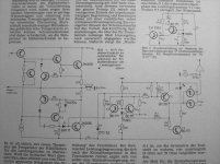
Your wondering and this question can be also valid for the whole Audio-DIY In the attachment is shown a audio claas B amp which uses the BE diode of the negative output transistor to measure its temperature when the positive transistor conducts.
If the temperature is too high the amp input would be disabled.
This simple circuit watched two channels (the not shown one is connected to T3a) The autor assumes a ac-coupled amp so its not really necessary to watch boths polarities.
(article is from mag Funk-Technik6 1974 autor J. Becker)
John,
when its not too much effort: I like to see Your circuit although
I not intend to use it nowadays.
Regards
Heinz!
Attachments
- Status
- This old topic is closed. If you want to reopen this topic, contact a moderator using the "Report Post" button.
- Home
- Design & Build
- Parts
- Heatsink calculations