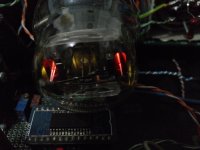
hi all..today i opened my tube DAC for some tunings and i found my AZ1 rectifier has a white lines on the upper heater filaments (the triangle)
is it sign of wear-out tube?..or it's no problem?
also, is there any ways to reduce the heater voltage?..at the first time i build my DAC, the heater was almost 5V (damn local custom transformer )
)
but now it's 6V!
i don't want to kill my AZ1 but i also don't want to waste my money for new transformer
thanks
n.b i attached the picture.sorry for crap quality.
is it sign of wear-out tube?..or it's no problem?
also, is there any ways to reduce the heater voltage?..at the first time i build my DAC, the heater was almost 5V (damn local custom transformer
)but now it's 6V!
i don't want to kill my AZ1 but i also don't want to waste my money for new transformer
thanks
n.b i attached the picture.sorry for crap quality.
Attachments
^^
It looks like that part of the filament is running slightly hotter since it's not covered by the cathode coating as it's above the plate. Since it's happening on both sides, this looks normal.
"also, is there any ways to reduce the heater voltage?..at the first time i build my DAC, the heater was almost 5V (damn local custom transformer )
but now it's 6V!"
Variac.
Regards the power transformer,
Have you thought the transformer may have been made correctly and the line voltage on you house mains is changing?
Reducing the heater voltage..do you have NTC surge suppression to reduced the power on surge on the supply?
Regards
M. Gregg
Have you thought the transformer may have been made correctly and the line voltage on you house mains is changing?
Reducing the heater voltage..do you have NTC surge suppression to reduced the power on surge on the supply?
Regards
M. Gregg
Last edited:
The AZ1 directly heated full wave rectifier is fitted with an eight pin side contact base. These bases were used originally by Philips in Europe and Mullard in the UK for universal valves from the 1930s. Universal meant valves for AC or DC supplies. When the Ct8 base proved unpopular in the UK some of the valves were re-issued on a standard International Octal base. For the AZ1 the re-issue was be the AZ31 with identical electrical characteristics.
It has a 4 Volt filament rated at 1.1 Amp. The maximum anode RMS voltage is 500 Volts. At this anode Voltage the DC current could be up to 60 mA. At 400 Volts on the anode the output could rise to 75 mA and with 300 Volts on the anodes the output current could be 100 mA. The maximum reservoir capacitor had to be no more than 60 µF.
The anode cavities are grey treated to radiate more heat and are probably made of Nickel.
The classic envelope is 46 mm in diameter and, excluding the Ct8 base pins, is 98 mm tall
6Volts will kill the heaters!
Yes correct..nice one 4V heater..
AZ1 @ The National Valve Museum
The heater voltage needs to come down...
Regards
M. Gregg
AZ1 @ The National Valve Museum
The heater voltage needs to come down...
Regards
M. Gregg
Last edited:
i've been made 2 custom transformer from a local company.the 1st one was so much wrong.20v and 40v for 4v and 5v output .so i returned them and the 2nd one was 4.5v and 5.xxv.
i'm sure i used the 4V tap and the transformer got almost 5V after i plugged the AZ1.
but today, i was surprised the voltage raised to 6V.
i dont want spend my money for another transformer
but i also don't want to kill my AZ1.
for NTC, i don't have them since i used dual switch.when i turn it on, i switched to a diode to let the filament heated and all caps charged.
Jon, i would to know how long can this AZ1 survive at 6v?..i was unplugged my AZ1 now for the safe
.so i returned them and the 2nd one was 4.5v and 5.xxv.i'm sure i used the 4V tap and the transformer got almost 5V after i plugged the AZ1.
but today, i was surprised the voltage raised to 6V.
i dont want spend my money for another transformer
but i also don't want to kill my AZ1.
for NTC, i don't have them since i used dual switch.when i turn it on, i switched to a diode to let the filament heated and all caps charged.
Jon, i would to know how long can this AZ1 survive at 6v?..i was unplugged my AZ1 now for the safe
If it was me,
This is just a try and see...and its a messy way to get round it.
I would try the following and see if it had an adverse effect on sound etc.
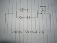
1....put two diodes in series with each other in series with the heater and put another two in series in inverse parallel across the first two and see what voltage I had across the heater. don't get them in series with any HT just the heater winding. They have to be rated for the current ie more than start up surge.
So you will get one half of the AC through the first two with a volt drop and the other half of the AC through the other two with a voltage drop.
you will get a voltage drop across the diodes it might be enough..its just something to try...
2...put a NTC in series with the heater and see what voltage I had after it warmed up. However it will get hot so watch placement.
Regards
M. Gregg
This is just a try and see...and its a messy way to get round it.
I would try the following and see if it had an adverse effect on sound etc.
1....put two diodes in series with each other in series with the heater and put another two in series in inverse parallel across the first two and see what voltage I had across the heater. don't get them in series with any HT just the heater winding. They have to be rated for the current ie more than start up surge.
So you will get one half of the AC through the first two with a volt drop and the other half of the AC through the other two with a voltage drop.
you will get a voltage drop across the diodes it might be enough..its just something to try...
2...put a NTC in series with the heater and see what voltage I had after it warmed up. However it will get hot so watch placement.
Regards
M. Gregg
Last edited:
OK think like this.
if you put two diodes in series with each other you will get a forward voltage drop...that would half wave the AC heater supply then put another two across the first two and you will conduct the other half of the cycle with another voltage drop.
They would have to take the current...it might be worth a try..
Regards
M. Gregg
Attachments
Last edited:
oh!..i got it.like 2 diodes being antiparalleled but instead of just 2, this used 2 series diode being antiparalleled?
sorry for my bad english
Look at post 10..drawing
Regards
M. Gregg
if you put two diodes in series with each other you will get a forward voltage drop...
Why would you want to add diode switching noise to your B+??
Just put some cheap wirewound power resistors in series with the heater supply.
edit: kevinkr was quicker to post.
Strange reading you have there. Is your meter correct? Flat battery maybe?
yes..my meters are runs out of battery..but after i used an analogue meter, not much difference..i'll just use an AVR then
source here aren't stable enough..sometimes they dropped to almost 190V, and sometimes fluctuated to almost 250V

- Status
- This old topic is closed. If you want to reopen this topic, contact a moderator using the "Report Post" button.
- Home
- Amplifiers
- Tubes / Valves
- heater wear sign?