oh, I get it. the original designer had only that Hammond transformer at hand and used the resistors just for dropping the voltage.
PS: I've been avoiding to call it a PI filter as AFAIK the nomenclature refers strictly to the case when a series inductor is used
You can use resistor to make pi filter but it is not as effective as inductor or
choke and much more expensive but sometimes it's better than
capacitor only filtering but you need higher incoming voltage thus higher
secondary voltage to account for the voltage drop across the filter.
regards.
IMO, it's important to find out if you're experiencing 100Hz or 50Hz hum. Without reference, the two can be difficult to tell apart. 100Hz hum would point towards a power supply filtering issue, while 50Hz would sooner point towards grounding or shielding issues.
As other users suggested: try simulating the power supply using the Duncan tool and see for yourself what the effect is of omitting the resistors from the power supply.
Oh and btw, I wouldn't be too worried of dropping the anode voltage a couple of volts (10 or 15) by adding the required resistors to the power supply. The loss in gain will be less than you might expect, and in a real life situation it probably won't be any problem at all in your case.
They are rather important in filtering the anode voltage. So their primary function is to prevent power supply hum from entering the circuit. I would strongly advise using a CRCRC filter or CLCRC filter instead of just parallel capacitors. If the 348V supply line is indeed only filtered with some parallel capacitors (and no Pi filter), it doesn't surprise me that you experience hum issues.the original PS has a parallel cap / series resistor / parallel cap / series R / parallel C topology. the implementation I own omits the series resistors. how critical are those resistors?
As other users suggested: try simulating the power supply using the Duncan tool and see for yourself what the effect is of omitting the resistors from the power supply.
Oh and btw, I wouldn't be too worried of dropping the anode voltage a couple of volts (10 or 15) by adding the required resistors to the power supply. The loss in gain will be less than you might expect, and in a real life situation it probably won't be any problem at all in your case.
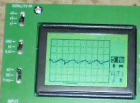
tell you what, I'll use my jyetech portable oscilloscope for the first time and see if it's PS ripple or smth elseIMO, it's important to find out if you're experiencing 100Hz or 50Hz hum. Without reference, the two can be difficult to tell apart. 100Hz hum would point towards a power supply filtering issue, while 50Hz would sooner point towards grounding or shielding issues.
They are rather important in filtering the anode voltage. So their primary function is to prevent power supply hum from entering the circuit. I would strongly advise using a CRCRC filter or CLCRC filter instead of just parallel capacitors. If the 348V supply line is indeed only filtered with some parallel capacitors (and no Pi filter), it doesn't surprise me that you experience hum issues.
As other users suggested: try simulating the power supply using the Duncan tool and see for yourself what the effect is of omitting the resistors from the power supply.
Oh and btw, I wouldn't be too worried of dropping the anode voltage a couple of volts (10 or 15) by adding the required resistors to the power supply. The loss in gain will be less than you might expect, and in a real life situation it probably won't be any problem at all in your case.
")
and I have a lot of chokes lying around... would the inductance matter a lot?
Oh man, if you'd told us right away you had a 'scope sitting on your desk, we would have urged you to use it much sooner! Definitely do some measurements with the scope and report back if it's 100Hz or 50Hz!
As to the inductance: just run a sim with the Duncan amp's tool and see for yourself. But generally speaking, as this is a quite low-load, high impedance application, you'll probably want to pick a relatively high inductance.
Definitely do some measurements with the scope and report back if it's 100Hz or 50Hz!As to the inductance: just run a sim with the Duncan amp's tool and see for yourself. But generally speaking, as this is a quite low-load, high impedance application, you'll probably want to pick a relatively high inductance.
ok guys, just measured the output. with the headphones on it's too low to measure with my modest scope (0.1V/div highest sensitivity) but w/o load it's clearly visible. it's 100Hz and the sawtooth shape suggest PS ripple. now I'll start winding an inductor as the largest I have is about 200u.
Attachments
Put back the resistors which should never have been omitted from the power supply. This will do two things: smooth the HT supply, make the charging pulses a bit more gentle. Ask your supplier why he omitted them; is he stupid, or does he think you are?
If you are worried about voltage drop then you could use lower value resistors.
If you are worried about voltage drop then you could use lower value resistors.
Yeah, I agree. Don't start winding chokes yet; it's much quicker to just put some resistors of the right value & power rating in there and see if the situation improves (it will, but try anyway). Then decide if you want to go through the trouble of winding a many-H inductor. Personally, I don't think it'll be necessary.
nevermind, it's a really old purchase.
too late, I wound a quick choke, stopped when the wire finished turned out to be about 20mH. the effect was that the hum dropped by a significant amount but was replaced with one of a lower frequency (I'd say below 50Hz?) and lower intensity too. but then I cut another PCB trace and soldered a 300 ohm resistor and... voila! hum disappeared almost completely. had to really listen to notice it. the voltage dropped with only ~6V. now let me check with another one fitted between the 2nd and 3rd caps.
too late, I wound a quick choke, stopped when the wire finished
turned out to be about 20mH. the effect was that the hum dropped by a significant amount but was replaced with one of a lower frequency (I'd say below 50Hz?) and lower intensity too. but then I cut another PCB trace and soldered a 300 ohm resistor and... voila! hum disappeared almost completely. had to really listen to notice it. the voltage dropped with only ~6V. now let me check with another one fitted between the 2nd and 3rd caps.both resistors fitted now (270 ohm as these were smaller and fit beneath the PCB) but still there's a tiny bit oh hum left. sounds still like 100Hz. not annoying but still noticeable. I'll try to see if I find a 3rd resistor since I have a bank of 4 caps. with these 2 the output voltage of the PS is 302V.
now, about R5 and other resistors. can I safely revert back to the original (BB's) values with this supply voltage (302 instead of 348V)?
LE: the 3rd (300 ohms) res lowers the hum some more but not by a significant amount so it's still mains ripple. maybe time for a really large choke?
now, about R5 and other resistors. can I safely revert back to the original (BB's) values with this supply voltage (302 instead of 348V)?
LE: the 3rd (300 ohms) res lowers the hum some more but not by a significant amount so it's still mains ripple. maybe time for a really large choke?
Last edited:
Hi Mr.Push_Pull,
You are not seeing the whole picture.If you want to use
the original resistor values of the BB circuit,are you saying that the power transformer has the 250Vac secondary? If yes then of course but if not then
even if you use the BB resistor values the circuit operational bias would
also change which defeat the purpose.As someone pointed out with BB bias
it is 10mA and at present with 1K resistor it is 3mA.But to be sure with your
current anode voltage you should measure the voltage across the 1K resistor
and calculate the current with ohm's law V devide by resistance.Only then can
you decide with the help of 6N1P curves where you think it will have the best
performance or sound.Better yet survey other 6N1p circuits and have a feel
of what is commonly used.
It is basically low current vs high current,with low current your
tube last longer and vice versa.How it sounds is another question.The new resistor values are not that far off from the BB circuit.You must understand
how tube circuit work before you try to change anything.As it is now your anode voltage is 305V (after power filter) vs 348Vdc ,that's a lot by the way.Let's put it this
way at what anode voltage do you want at 6N1P? Then make the neccesary
changes.
I think the 270 ohm for pi filter is small compare with audionote
M7 preamp as example it uses 2K.Going more than 4 stages has diminishing
return of the filter.Better yet get a 10H - 15H choke if you diy you need lots
of wire.Ultimately it's the anode voltage or operating point and cathode bias that is important.
edit: By anode voltage I mean the voltage at the tube anode or the lower end of the anode resistor closest to the tube.
regards.
Last edited:
that's why I'm asking here. like I said, I'm really "tube-challenged" and I make efforts to read a schematic that contains tubesHi Mr.Push_Pull,
You are not seeing the whole picture.
triode, grid, plate, all novelties to me.just had a conversation with a friend that has a degree in EE and he told me that in order to make the circuit work as close as it was designed to I need to first adjust R3 so that voltage on the anode of the input triode reaches about VDC/2 (151V in my case) and then adjust voltages on the plates of the output ones using R4 and R5, trying to mantain the desired bias current. and that I need to mantain the voltage on the anode of the lower output triode slightly higher than that of the input triode. did I get this right?
Yes, you got it right. But the first half is debatable:
In a sense, the bloke who built your amp already decided for you: he used a transformer with a relatively low secondary voltage, limiting the anode voltage on the tubes. Secondly, he decided to run the output pair at a conservative rating. You could decide to follow that decision and bias conservatively. If you change none of the resistor values in the amplifier part, you will reach a bias point which is even more conservative than in your original schematic, due to the lower V+.
You could also try to bias at a comparable point to the situation before you 'upgraded' the power supply Pi filters. this will involve lowering some resistor values (you'll have to get out the tube curves and do the math); you'll need to adjust R3-R5 and probably R2 as well to keep the gain of the first stage at the original level.
But you could also decide you want to bias the whole amplifier much hotter (closer to the Headwize original). If you decide on that, take into account that the power supply will likely require more adjusting, because as you draw more power from it, ripple (hum) will increase and more filtering will be necessary (further lowering the output voltage).
So there's many things you can do. Perhaps the wisest thing to do now is listen to it as it is, and decide which route you want to take. The current situation is probably far from optimal in terms of distortion and power output, but you might not even notice this yourself. Listen carefully to your amp, and try to put your finger on what you're missing in its sound.
You're definitely in the right track eliminating hum; it shows you're critical, which tends to lead to improvement!
It's not only the anode voltage of the 6n1p you're optimizing for, but the working point, which includes the tube's idle current. This would be the time to get out the curves of the 6n1p and decide on a suitable working point. As Singa pointed out, it's very much a matter of taste; some like to run their tubes hot (relatively high current; pushing the tube closer to overdrive, resulting in more even harmonics and generally a 'warmer' sound), while others prefer to run their valves at a more conservative rating, resulting in a 'cleaner' or 'more precise' audio reproduction. Note the rather subjective qualifications I put between quotes; this is the point where electrical engineering intersects with artistic subjectivity, if you will.adjust R3 so that voltage on the anode of the input triode reaches about VDC/2 (151V in my case)
In a sense, the bloke who built your amp already decided for you: he used a transformer with a relatively low secondary voltage, limiting the anode voltage on the tubes. Secondly, he decided to run the output pair at a conservative rating. You could decide to follow that decision and bias conservatively. If you change none of the resistor values in the amplifier part, you will reach a bias point which is even more conservative than in your original schematic, due to the lower V+.
You could also try to bias at a comparable point to the situation before you 'upgraded' the power supply Pi filters. this will involve lowering some resistor values (you'll have to get out the tube curves and do the math); you'll need to adjust R3-R5 and probably R2 as well to keep the gain of the first stage at the original level.
But you could also decide you want to bias the whole amplifier much hotter (closer to the Headwize original). If you decide on that, take into account that the power supply will likely require more adjusting, because as you draw more power from it, ripple (hum) will increase and more filtering will be necessary (further lowering the output voltage).
So there's many things you can do. Perhaps the wisest thing to do now is listen to it as it is, and decide which route you want to take. The current situation is probably far from optimal in terms of distortion and power output, but you might not even notice this yourself. Listen carefully to your amp, and try to put your finger on what you're missing in its sound.
You're definitely in the right track eliminating hum; it shows you're critical, which tends to lead to improvement!
mastodon So there's many things you can do. Perhaps the wisest thing to do now is listen to it as it is said:Mastadon you say more eloquently and better than me so take over from here.
Mr.Push_Pull take it easy,I too took a long time to fiqure it out
and am still learning like you.Hope you don't take this personally.
But once you get it that's where the fun begins.
Ps go to Pete Millett website and download some tube design books.Like Radiotron ed.3 and 4.
and anything that interest you.It's a goldmine of information.
Last edited:
I saw that the description of the original MJ design (linked to on the BB design page) is much more detailed, maybe I'll manage to reach a better result if I can understand what happens there. there's even a version with global feedback... more to experiment.Yes, you got it right. But the first half is debatable:
It's not only the anode voltage of the 6n1p you're optimizing for, but the working point, which includes the tube's idle current. This would be the time to get out the curves of the 6n1p and decide on a suitable working point. As Singa pointed out, it's very much a matter of taste; some like to run their tubes hot (relatively high current; pushing the tube closer to overdrive, resulting in more even harmonics and generally a 'warmer' sound), while others prefer to run their valves at a more conservative rating, resulting in a 'cleaner' or 'more precise' audio reproduction. Note the rather subjective qualifications I put between quotes; this is the point where electrical engineering intersects with artistic subjectivity, if you will.
In a sense, the bloke who built your amp already decided for you: he used a transformer with a relatively low secondary voltage, limiting the anode voltage on the tubes. Secondly, he decided to run the output pair at a conservative rating. You could decide to follow that decision and bias conservatively. If you change none of the resistor values in the amplifier part, you will reach a bias point which is even more conservative than in your original schematic, due to the lower V+.
You could also try to bias at a comparable point to the situation before you 'upgraded' the power supply Pi filters. this will involve lowering some resistor values (you'll have to get out the tube curves and do the math); you'll need to adjust R3-R5 and probably R2 as well to keep the gain of the first stage at the original level.
But you could also decide you want to bias the whole amplifier much hotter (closer to the Headwize original). If you decide on that, take into account that the power supply will likely require more adjusting, because as you draw more power from it, ripple (hum) will increase and more filtering will be necessary (further lowering the output voltage).
So there's many things you can do. Perhaps the wisest thing to do now is listen to it as it is, and decide which route you want to take. The current situation is probably far from optimal in terms of distortion and power output, but you might not even notice this yourself. Listen carefully to your amp, and try to put your finger on what you're missing in its sound.
You're definitely in the right track eliminating hum; it shows you're critical, which tends to lead to improvement!
Last edited:
I built both... always worth a try...there's even a version with global feedback... more to experiment.
I'll second Mastodon to have a look at the triode curves of the 6N1P... it is not as difficult as it looks at first and will give you a good understanding what is happening.
There is also some easy to understand information here -->How to design valve guitar amplifiers
You seem to have a good understanding so hang on in...
thanks for the link!There is also some easy to understand information here -->How to design valve guitar amplifiers
at a quick glance that seems to be exactly what I need. al my generic searches sent me to pages which were either too general or went into way too much details.
yesterday I was very close to finding out the hard way that working late and high voltage-powered tube gear don't mix well.
I was doing some testing with my Grados on (as in on my head) and connected to the amp when I shorted by accident one of the output wires with something on the board. a spark, a very loud pop in my left ear and smell of burnt parts. surprisingly the Grados survived, they seem to be completely unaffected, although the characteristic smell of burnt voice coil was present. the amp is OK too. I never forget to discharge the caps after powering the thing off but I was so clumsy when it was ON...
I guess it's time to put this aside for a while until have more spare time and I'm not forced to work late
PS: gave the thing a thourough listen with the added PS resistors and truth be told it doesn't sound bad at all as it is; really makes the otheiwise aggressive Grados sound very pleasant
after a long while I decided to finish fixing the amp. I replaced all the parts with the values from Bruce's schematic, replaced the transformer to give the right voltage and floated the heater ground with a 0.1u cap. result: all hum completely gone, no way to tell if the amp is on only by sound. and it sounds extremely good.

- Status
- This old topic is closed. If you want to reopen this topic, contact a moderator using the "Report Post" button.
- Home
- Amplifiers
- Tubes / Valves
- Headwize 6N1P OTL headphone amp having hum