HD-600s
Senneheiser HD-600s arrived today.
Nice headphones. Strange though.
When I first put them on they caused my hearing aids to switch to Telicoil. Aw Cr^p!
Then after a few seconds they switiched to mode 3on their own. Mode 3 is the custoom mode I had set up for listening to stereo and TV!
Looks like a keeper.
I'm looking at building a tube based headphone amp running a Mu Stage with a Parafeed output.
Senneheiser HD-600s arrived today.
Nice headphones. Strange though.
When I first put them on they caused my hearing aids to switch to Telicoil. Aw Cr^p!
Then after a few seconds they switiched to mode 3on their own.
Mode 3 is the custoom mode I had set up for listening to stereo and TV! Looks like a keeper.
I'm looking at building a tube based headphone amp running a Mu Stage with a Parafeed output.
Well, it took two visits to the VA to get the hearing aids adjusted so they don't switch modes when I wear headphones. But, they are finally adjusted to my satisfaction.
I've started working on the headphone amp. I've wound my first attempt at an output transformer, but haven't assembled the EI core in it yet. I made several mistakes when winding the core, so I plan on doing some testing with this one and then wind two more for the amp.
I've started working on the headphone amp. I've wound my first attempt at an output transformer, but haven't assembled the EI core in it yet. I made several mistakes when winding the core, so I plan on doing some testing with this one and then wind two more for the amp.
Prototype amp
Well, I'm not sure whether to put this here or in the Tube Amp section but it is about a Headphone System so I'll continue here:
I've got my hearing aids adjusted so I can wear headphones.
I've got a set of HD-600s which are 300Ohm impedance.
I've decided on a 71a Mu Follower Parafeed Headphone Amp to drive the headphones.
The 71a is an old directly heated triode (DHT) that was designed as an Audio Output tube specifice at a max of 0.79W out.
It uses 5.0V on the filament, and 180V anode to cathode.
Simulations under LTSpice look favorable with full output below 1%thd.
I figure it will need a driver as it only has a gain of 3, and the transformer I wound is a 6:1 step down transformer for a loss of 3dB overall.
So I selected the 37 or 76 as appropriate driver tubes. These are heater cathode tubes with gains of 9.2 and 13.8 respectivly.
Overall gain is thus either 4.6 (13.26dB) or 6.9 (16.78dB).
A volume control will be necessary preceeding the first driver tube.
Prototype of the output stage of the amplifier does not meet expectations.
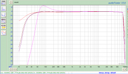
Frequency response is very good with LF -3dB around 15Hz and HF -3dB awella bove 100KHz.
Distortion is way higher than anticipated.
Well, I'm not sure whether to put this here or in the Tube Amp section but it is about a Headphone System so I'll continue here:
I've got my hearing aids adjusted so I can wear headphones.
I've got a set of HD-600s which are 300Ohm impedance.
I've decided on a 71a Mu Follower Parafeed Headphone Amp to drive the headphones.
The 71a is an old directly heated triode (DHT) that was designed as an Audio Output tube specifice at a max of 0.79W out.
It uses 5.0V on the filament, and 180V anode to cathode.
Simulations under LTSpice look favorable with full output below 1%thd.
I figure it will need a driver as it only has a gain of 3, and the transformer I wound is a 6:1 step down transformer for a loss of 3dB overall.
So I selected the 37 or 76 as appropriate driver tubes. These are heater cathode tubes with gains of 9.2 and 13.8 respectivly.
Overall gain is thus either 4.6 (13.26dB) or 6.9 (16.78dB).
A volume control will be necessary preceeding the first driver tube.
Prototype of the output stage of the amplifier does not meet expectations.
Frequency response is very good with LF -3dB around 15Hz and HF -3dB awella bove 100KHz.
Distortion is way higher than anticipated.
Attachments
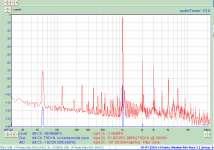
Well, for something with no negative feedback (if I'm getting that right) it's not doing too badly.Distortion is way higher than anticipated.
Guess why my enthusiasm for hollow state has been quite limited so far. Doing it right requires a fair amount of effort, what with input and output transformers, and when it's all done you've got a heavy, power-hungry monster - and then comes a circuit with pennies worth of opamps and transistors and runs circles around it. (Case in point: The O2.) Rather disconcerting, this.
You know what I might do if I wanted to get fancy?
Input stage - inverting op-amp, ~+6 dB, 5532 (though TL072 would be just fine for typical input impedances, too; anything better has near-zero practical relevance)
Volume pot - 10k, Alps something or other
Buffer - LM4562 or somesuch (mind bias currents)
Gain stage - inverting op-amp, ~+10 dB, 2k2/6k8 or so, w/ 2x 5534, LM4562, NJM2068 or similar (5532 if need be, even lower-noise types would be nice esp. with lower R values)
Buffer - single EF in Class A (20-75 mA) with BD139/140 or TIP31/32C or similar in gain stage feedback loop, or CFP (similar transistors with matching small-fry stuff) at similar current levels either in or outside of feedback (the latter may be easier to get stable, though the former would ensure lowest noise)
Power supply - nothing too fancy, +/- 15V from ordinary 78/7915 would be fine, though I might do a LM317/337 low-noise just for the heck of it
Optional niceties - Protection and turn-on delay, input gain select 0/+6/+12 dB
Yes, no feedback other than internal to the devices
I've come to the conclusion that my sound card (M-Audio AP192K) is damaged and generating some of the distortion. I'll change all the op-amps (NE5532ADR) in the output and input stages and hope that fixes it.
It looks like there may be enough gain in the single 71a stage to drive the headphones without resorting to the driver stage. I listened to Yusef Lateef "autophysiopsychic" last night and it sounded pretty good with just the 71a stage.
I could certainly do better on paper with solid state, but what would be the fun of that.
As far as power goes, I'm not concerned if I burn 20 Watts to listen to 100mW. Not a very green attitude, but ...
Before taking the shotgun approach, you may want to run some RMAA loopback tests. In ASIO mode (now available in the free version) you can select the output channels to use.I've come to the conclusion that my sound card (M-Audio AP192K) is damaged and generating some of the distortion. I'll change all the op-amps (NE5532ADR) in the output and input stages and hope that fixes it.
Well, instead of worrying about the basic stuff, you could worry about more advanced things at the same level of complexity / involvement (let's call it the "fuss level"). If in doubt, there'd still be any amount of fun to be had when going discrete and (highish) single supply with low semiconductor count. (That's sufficiently oldschool for me - I'm one of those young whippersnappers who're barely as old as the NE5532!I could certainly do better on paper with solid state, but what would be the fun of that.
) I do see where you're coming from though.I thought it interesting that you were using output but no input transformers. It's not that problematic with typical CD player levels, but when a volume control comes into play, I imagine it would not be ideal use of input-side dynamic range, plus the higher gain required. (Something like 1:2 to 1:4 would seem good.) I would also look into a plate choke, or the more economical MOSFET-based gyrator simulation thereof at least, for higher voltage swing and plate current (lower noise, better linearity) in the voltage amp stage. Also, from what I remember, an SRPP type circuit does not have particularly grand PSRR, so with extra voltage gain present, a conventional cathode follower w/ current source may be worth looking at.
Speaking of hybrid circuits - I might look into a conventional bipolar LTP (pnp input, cascoding with 160V+ transistors might be helpful) and a hybrid cascode VAS (BC550C or similar) with either an inductor or bootstrapped load, and then apply a good amount of feedback. Just throwing some random ideas out there... Nobody's forcing anyone to build tube circuits like 60 years ago, right?
That you are getting along fine with an effective -6 dB gain (I am not sure where you got -3 dB from) does not come too surprising - it has been found that unity gain tends to be ample when using the typical a-little-over-100-dB/V hi-fi cans with CD-player-alike source levels. A usual maximum 1 Vrms for 0 dBFS (about 4 mW into 300 ohms) does sound a little pedestrian though. A little Clip+ will easily drive its maximum 0.8 V into 300 ohms, and that tiny thing runs for over 10 hours on a measly 200 mAh, 3.7 V lithium battery which powers more than just the headphone driver - what a contrast. Well, I imagine it may not do both at the same time, but anyway.
Definatly a bad soundcard
I'm using an output transformer for impedance matching due to the high output impedance of the tube and circuit.
The topology is Mu Stage which is somewhat similar to SRPP, but has much better PSRR.
Aklan Kimmel has a good write up on it:
http://www.google.com/url?sa=t&rct=j&q=&esrc=s&source=web&cd=1&ved=0CCgQFjAA&url=http%3A%2F%2Fwww.fetaudio.com%2Fwp-content%2Fuploads%2F2003%2F09%2FMu-Stage.pdf&ei=MA4hU_S5Aunt0gHQyoGICg&usg=AFQjCNEHQrhI8wFfJ0HsrIcVFT9EAANrpw&sig2=hbEFT6NXZLqpABqXHcoKcQ&bvm=bv.62922401,d.dmQ
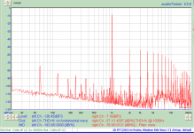
I ran a few tests and if I use an external signal generator the plots look about as I expect.
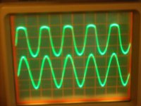
If I perform a loopback on the sound card outputs to inputs I get a lot of harmonics, which can even be seen if I look at the signal with an oscilloscope. Both top and bottom of the sine wave are clipped, although the negative going portion is clipped more.
So Either shotgun the op amp chain, or send it back to M-Audio for repair if they still work on them.
I'm using an output transformer for impedance matching due to the high output impedance of the tube and circuit.
The topology is Mu Stage which is somewhat similar to SRPP, but has much better PSRR.
Aklan Kimmel has a good write up on it:
http://www.google.com/url?sa=t&rct=j&q=&esrc=s&source=web&cd=1&ved=0CCgQFjAA&url=http%3A%2F%2Fwww.fetaudio.com%2Fwp-content%2Fuploads%2F2003%2F09%2FMu-Stage.pdf&ei=MA4hU_S5Aunt0gHQyoGICg&usg=AFQjCNEHQrhI8wFfJ0HsrIcVFT9EAANrpw&sig2=hbEFT6NXZLqpABqXHcoKcQ&bvm=bv.62922401,d.dmQ
I ran a few tests and if I use an external signal generator the plots look about as I expect.
If I perform a loopback on the sound card outputs to inputs I get a lot of harmonics, which can even be seen if I look at the signal with an oscilloscope. Both top and bottom of the sine wave are clipped, although the negative going portion is clipped more.
So Either shotgun the op amp chain, or send it back to M-Audio for repair if they still work on them.
Attachments
I've traced the circuit for the M-Audio Delta 192 sound card and it is pretty straightforward.
The buffer/low pass filter for the DAC AK4358) output looks like the recommended circuit the datasheet, with different values to get the 92KHz BW. The output is capacitivly coupled to the output drivers which are in turn capacitivly coupled to the output connector with what looks like a protection network on the output.
I have not determined what the SO23 devices are in the protection network, but they are not clamp diodes. Ref designator is Qxx which implies a transistor.
I should be able to look at the buffer/LP Filter output with a scope to see if the distortion is present there.
Well, I've looked at the signal starting at the output of the LPF with an oscilloscope and it looks fine all the way thorugh the final buffer amp at the output.
After it goes through a 150R resistor and the coupling cap to the clamp circuit, it gets clipped.
It could be the actual clamp device, or the reference voltage that is connected to it. The ref voltage is geenrated by two transistors in parallel (SOT-23s). So I guess it's time to contact M-Audio and see if they still repair them.
Mean time I checked the SB Audicy SE and it it perminatly looped back internally at -30dB so it is toast. I think it came from an old gaming system my son had years ago.
I've ordered a XONAR D1 RT to get me by with till I get the M-Audio fixed, if I can get it fixed.
Attachments
The Xonar D1 RT got me back to plots similar to post 24. It is not as clean as the M-Audio but will do until I can get The M-Audio fixed.
I tried several sets of tubes with pretty much the same results. I can adjust bias on each tube and change the distortion profile and get a lower total THD number, however the lower number is achieved by lowering 2nd harmonic content without effecting 3rd and subsequent harmonics very much.
Experience has shown that doing so makes an amp sound slightly bright and edgy.
I may try increasing the load resistors value to see if that decreases distortion, which it should as it will change DF. In order to accomplish that, I would have to change the turns ratio of the transformer which in turn would decrease output voltage. In the long run, it may be worth it.
The most I can get out of it currently is 1.5Vrms as above that level the sound card clips and distortion goes way up.
I won't be able to work on it for a week or so as I'm going to visit my kids out of state.
- Status
- This old topic is closed. If you want to reopen this topic, contact a moderator using the "Report Post" button.
- Home
- Amplifiers
- Headphone Systems
- Headphones and Hearing aids