My previous model had 2x2 MSR25 3.3R resistors in parallel in between the big power caps. This means roughly 3 ohm and 1.2W if I am not mistaken.
The 2 positions on the board are not big enough to fit 2W resistors nicely like the seller of the board advised. The 2W 3R resistors are hard to get anyway. I did find some wirewound black dales in this size (which are practically to big).
Also found some 3.01R Vishay Dale 1W metal film resistors which fit perfectly and fit the bill better. I think the 0.6W resistors on this board are overkill anyway because I replaced most of them with 1/4 versions.
Sooo anyone that can give me a calculation ande explanation on whether a 1W resistor would be sufficient to replace the two smaller 3.3R 0.6W resistors of the original model.
How is it they can discharge faster? Because of smaller capacity? Because other parameters are definately not in favor of 10uF tantalum...Also decided not to use radial electrolytes for the small 10uf LM317 mod but ordered some genuine Spraque 10uf 35V tantalums to put in this position for the charge en decharge WAY faster than the slow Elna Silmic IIs.
No way 10uF tantalum has ESR lower than 100uF silmic. In fact 100uF/25 silmic has 0.2 ohm ESR to 100khz, from what i briefly checked tantalums of 10uF/35V have around 0.45. Not that it correlates with sound much anyway..
I think the only reason sometimes people think Silmic are "slow" is because they do not highlight upper range as much as others due to low tan and DA probably. They are actually very low esr caps, second to panasonic FM and lower than FC for example
I think the only reason sometimes people think Silmic are "slow" is because they do not highlight upper range as much as others due to low tan and DA probably. They are actually very low esr caps, second to panasonic FM and lower than FC for example
Last edited:
I got some. SILMIC ARS caps also some panasonics all in 10uf 35V and 50V. The 50V will even have lower ESR. I also got some bipolar panasonics and Elna's in this capacity so I will pick some. When I have received them all I will make some pictures and you guys can help me make a selection.
Last edited:
No way 10uF tantalum has ESR lower than 100uF silmic. In fact 100uF/25 silmic has 0.2 ohm ESR to 100khz, from what i briefly checked tantalums of 10uF/35V have around 0.45. Not that it correlates with sound much anyway..
I think the only reason sometimes people think Silmic are "slow" is because they do not highlight upper range as much as others due to low tan and DA probably. They are actually very low esr caps, second to panasonic FM and lower than FC for example
I wasn't comparing a 10uf tantalum to a 100uf silmic but 10uf to 10uf.
Tantalums are known for their speed. But unfortunately also their instability and a lot of audio engineers advise against them even with counter measures taken around them in the circuit.
I ordered a shitload of 10uf capacitors ranging in between 35V and 63V. Elnas, Panas, Nippons, spraques etc. We will see what sounds best.
Finally got myself some genuin LXZ caps (470uf/25V and 560uf/35V. The rest I don't know). Also got some other Nippon KZM and some Panasonic FR and FM caps. Will try them all out.

When we purely look at specs, the KZM and FR are the best specs and have nearly identical specs. Although the LXZ and the FM are bigger and look more fancy, if we look purely at specs they come second. Now that made me wonder.. When I first got the FR caps I was already unpleasantly surprised by their ugly and common appearance. Why would they put more effort in designing the FM caps than the (supposedly) superior FR caps.. The FMs are often more expensive too than the FRs. For the Nippon it's the same story. The LXZ look way more appealing with their shiny almost metallic coating than the boring non-glossy brown KMZs.. Same story here. KMZs are better on paper and smaller.. what is going on? Why did Lehmann choose the LXZ caps over the smaller KMZs? Why are FRs cheaper than FMs? etc etc..
When we look at specs the KMZs are equal to the FRs and the FMs are almost equal to the LXZs.
I will put this to the test and do listening myself if I can spot any differences between them.. They are all GOOD caps! So maybe finding a difference will be a hard thing to do but I will at least try!
Also got some caps for the bypass positions now housing the Wima FKP4 0.022nm caps. Some caps I don't even know the brand from.. but the Shin Shin (polystyrene) caps look promising considering specs and size.
General progress:
Also had a little setback. My new case came in.. and it was a LOT smaller than my previous one from Jays audio. The quality was also lower. Thiner and smaller frontplate. Inferior and very rough paint. Volume knob painted wait to shiny and rough. Inner housing not painted. Letters on front panel of poor quality (even though they say Lehmann audio). But this was the only case the PCB I chose would fit in nicely so these things could be overcome. What I could not overcome was that my 60VA Block transformer wouldn't fit! Not by FAR! So this would mean my expensively (from Europe to China) imported 60VA transformer would be useless and I would have to use a 40VA Block transformer that I still have lying around. Probably the 40VA high quality transformer would do the job fine but this will be a ultimate build with most components maxed out so I can see where the limits of this circuit lay.
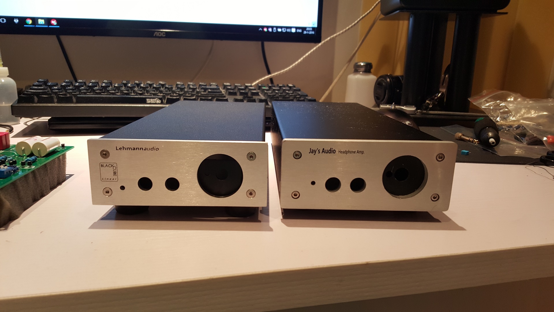
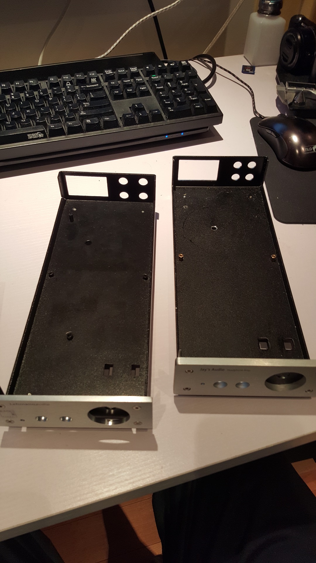
I will save the case for another build later, but for now I will customize the PCB and case a bit to fit together. This won't be a huge problem but I would have liked a solid PRO build without to much customizing everything.. I don't want it to be a scrapyard build. Must be clean and PRO for daily use.
Still waiting for some resistors, mundorf 4700uf 40V (63V didn't fit! not even in the big case) and some smaller 10uf caps.
I hope everything will come in this weekend! So I can get it running and start fine tuning with different caps and opamps.
When we purely look at specs, the KZM and FR are the best specs and have nearly identical specs. Although the LXZ and the FM are bigger and look more fancy, if we look purely at specs they come second. Now that made me wonder.. When I first got the FR caps I was already unpleasantly surprised by their ugly and common appearance. Why would they put more effort in designing the FM caps than the (supposedly) superior FR caps.. The FMs are often more expensive too than the FRs. For the Nippon it's the same story. The LXZ look way more appealing with their shiny almost metallic coating than the boring non-glossy brown KMZs.. Same story here. KMZs are better on paper and smaller.. what is going on? Why did Lehmann choose the LXZ caps over the smaller KMZs? Why are FRs cheaper than FMs? etc etc..
When we look at specs the KMZs are equal to the FRs and the FMs are almost equal to the LXZs.
I will put this to the test and do listening myself if I can spot any differences between them.. They are all GOOD caps! So maybe finding a difference will be a hard thing to do but I will at least try!
Also got some caps for the bypass positions now housing the Wima FKP4 0.022nm caps. Some caps I don't even know the brand from.. but the Shin Shin (polystyrene) caps look promising considering specs and size.
General progress:
Also had a little setback. My new case came in.. and it was a LOT smaller than my previous one from Jays audio. The quality was also lower. Thiner and smaller frontplate. Inferior and very rough paint. Volume knob painted wait to shiny and rough. Inner housing not painted. Letters on front panel of poor quality (even though they say Lehmann audio). But this was the only case the PCB I chose would fit in nicely so these things could be overcome. What I could not overcome was that my 60VA Block transformer wouldn't fit! Not by FAR! So this would mean my expensively (from Europe to China) imported 60VA transformer would be useless and I would have to use a 40VA Block transformer that I still have lying around. Probably the 40VA high quality transformer would do the job fine but this will be a ultimate build with most components maxed out so I can see where the limits of this circuit lay.
I will save the case for another build later, but for now I will customize the PCB and case a bit to fit together. This won't be a huge problem but I would have liked a solid PRO build without to much customizing everything.. I don't want it to be a scrapyard build. Must be clean and PRO for daily use.
Still waiting for some resistors, mundorf 4700uf 40V (63V didn't fit! not even in the big case) and some smaller 10uf caps.
I hope everything will come in this weekend! So I can get it running and start fine tuning with different caps and opamps.
Attachments


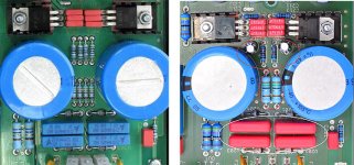
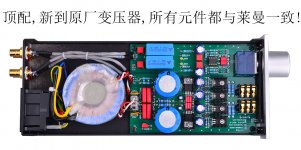
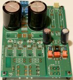
This I pulled of one of the Taobao shops. I got my PCB from him.. really arrogant bastard. Doesn't want to explain anything. Doesn't want to sell the rev7 pcb only when I am buying a full device. I bought the Rev5 PCB, asked about what resistors he uses in between the 2 power caps, and got an answer not to disturb him.
Well he's an ***.. that's for sure.. but he is doing quite some interesting stuff. I think it's based on the latest revision of the original Lehmann. Actually I think it is the real Lehmann in the picture with the blue transformer because he is using black closed ones.
I think the new design incorporates different resistor values and the use of a couple of 10uf caps.. It's a shame I can't see the backside of the pcb on this one..
It's interesting though. It's another version of the PSU mod everybody is already doing. I think Lehmann evolved too..
Look at the small caps instead of resistors..
Attachments
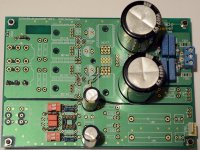
Started to populate my second BCL today.
The first one worked for several years before something went wrong and two of the caps got swollen, swapped them and the same two(same position that is) got hot(ter) than the others.
That was an assembled kit I got marked JSDZ or similar.
It was a real PITA to de-solder parts from that PCB I remember, no clue what solder was used when it was built...
Anyway, got a green board cheap and figured why not add that to the list of headamps I'm currently building lol
Having read through this thread quickly, I figured that though the old one never had any grounding issues..why not make sure while the PCB is empty?
So far I've only used parts I had at home already.
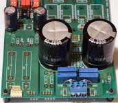
Vishay, ERO and Roederstein resistors, Wima FKP2, Panasonic FC, NCC KMG and Epcos caps and I used BYV95A diodes for the diode bridge.
I have some Dale RN60D 1K5 on the way along with Vishay MRS25 47R, Vishay MPR24 47R and Vishay MR30 3R3.
I have Icel MPL 2.2uF's, Arcotronics MPK C.4G 2.2uF and some radial MKP's ranging from 1uF to 4.7uF to chose from to use as input caps.
I have Vishay 100R, unknown 1% metal film 1K1 (and some Allen Bradley's but they are for a tube build) and just two (unfortunately) Riken 10R 3W...though I don't know that they'd fit anyway.
Speaking of the 10R's on the output, I have a pair of Fidelio X2 HP's that are only 30ohms...If I properly heatsink the output BJT's, I could probably use lower value output resistors?
Any suggestions on value?
I'll use a Philips KP axial for the 1000pF, Philips MKP's for the 22nF.
The Pana FC's are 1000uF/35V, I'll use those for all lytics except the two large PS caps (NCC KMG 6800uF/50V).
Thinking about doing the vreg mods suggested in this thread, I have the Zeners and possibly the lytics to replace the two 0.15uF caps.
That's an odd value btw (for those spots), I have plenty of Wima and BC 100nF, 220nF and so on, but just one 150nF in my parts.
Having a bit of trouble sourcing the the resettable fuses, so I might just jumper those, or put 5x20mm fuseholders on the PCB using doublesided tape and wire them to the PCB. I'll need to convert the fuse value first though.
Anyway, this is as far as I got today. (I have a few other builds going on besides this one)
Thanks for an interesting thread")
The first one worked for several years before something went wrong and two of the caps got swollen, swapped them and the same two(same position that is) got hot(ter) than the others.
That was an assembled kit I got marked JSDZ or similar.
It was a real PITA to de-solder parts from that PCB I remember, no clue what solder was used when it was built...
Anyway, got a green board cheap and figured why not add that to the list of headamps I'm currently building lol
Having read through this thread quickly, I figured that though the old one never had any grounding issues..why not make sure while the PCB is empty?
An externally hosted image should be here but it was not working when we last tested it.
before the parts in the pic was mounted.So far I've only used parts I had at home already.
Vishay, ERO and Roederstein resistors, Wima FKP2, Panasonic FC, NCC KMG and Epcos caps and I used BYV95A diodes for the diode bridge.
An externally hosted image should be here but it was not working when we last tested it.
I have some Dale RN60D 1K5 on the way along with Vishay MRS25 47R, Vishay MPR24 47R and Vishay MR30 3R3.
I have Icel MPL 2.2uF's, Arcotronics MPK C.4G 2.2uF and some radial MKP's ranging from 1uF to 4.7uF to chose from to use as input caps.
I have Vishay 100R, unknown 1% metal film 1K1 (and some Allen Bradley's but they are for a tube build) and just two (unfortunately) Riken 10R 3W...though I don't know that they'd fit anyway.
Speaking of the 10R's on the output, I have a pair of Fidelio X2 HP's that are only 30ohms...If I properly heatsink the output BJT's, I could probably use lower value output resistors?
Any suggestions on value?
I'll use a Philips KP axial for the 1000pF, Philips MKP's for the 22nF.
The Pana FC's are 1000uF/35V, I'll use those for all lytics except the two large PS caps (NCC KMG 6800uF/50V).
Thinking about doing the vreg mods suggested in this thread, I have the Zeners and possibly the lytics to replace the two 0.15uF caps.
That's an odd value btw (for those spots), I have plenty of Wima and BC 100nF, 220nF and so on, but just one 150nF in my parts.
Having a bit of trouble sourcing the the resettable fuses, so I might just jumper those, or put 5x20mm fuseholders on the PCB using doublesided tape and wire them to the PCB. I'll need to convert the fuse value first though.
Anyway, this is as far as I got today. (I have a few other builds going on besides this one)
An externally hosted image should be here but it was not working when we last tested it.
Thanks for an interesting thread
Having read through this thread quickly, I figured that though the old one never had any grounding issues..why not make sure while the PCB is empty?
Why do you think the board have grounding issues?
Why do you think that isolating signal ground from power ground without even a resistor to bridge them is a good idea?
Did you realized that in this way you also introduced a ground plane slot on signal traces that goes from opamp out to the diamond buffer input?
I will put a ferrite bead parallelled with a film cap between the separate gnd's. Unless that is a bad idea in your opinion?
I read something about the modifications earlier in this thread IIRC?
Should it turn out to be a bad idea I guess some thick Cu tape over the cut, connected to GND would more or less "restore" the GND plane?
I did not write my plan for connecting the gnd's, and text conversations have a tendency to be misunderstood...
My board has no grounding issues. They are evolved versions engineered by people who know what they are doing and next to that the boards are nearly 1:1 Lehmann clones.
I am wondering about the zener diode mod. We are removing 2 1.1K resistors te replace them with diodes that definitely have a different internal resistance. Will this not create a totally different voltage across the board? I know we are placing little capacitors right after that that may re-balance things a bit again but I am a bit confuse about how this mod actually works and how the system benefits from this. Can some one try to explain it to me a bit more? for the sake of understanding what I am doing instead of just blindly following what others have done before me. hehe!
I am wondering about the zener diode mod. We are removing 2 1.1K resistors te replace them with diodes that definitely have a different internal resistance. Will this not create a totally different voltage across the board? I know we are placing little capacitors right after that that may re-balance things a bit again but I am a bit confuse about how this mod actually works and how the system benefits from this. Can some one try to explain it to me a bit more? for the sake of understanding what I am doing instead of just blindly following what others have done before me. hehe!
Last edited:
I would be very interested in testing your finished machine against mine to see if my product choices are really worth it.
Not to be disrespectful but I already see you use a lot of inferior parts that I definitely would not have chosen and your way of connecting the signal cables is also definitely not preferable to soldering them in place. (I tried something like this with halved dip8 sockets of high quality and this was already problematic in terms of a solid connection. Your solution is even less solid with the pc fan connector.)
If I am not mistake I see Panasonic FC caps near the opamp? They are not well suited for this position. I found them to be empty and hollow against the Panasonic Pureisms and Elna Silmics in this position. FCs will be good at the PSU output though but even there are better choices to be made than the FCs for just the same money.
I am very interesting what end result you will achieve. What is your goal with this project?
I personally would advise you to not just use parts you still have lying around but select better parts for your project that are well suited for their function. The orignal Lehmann is a highly tuned device. And most of the parts are chosen with care for a good overal result. Just putting in random parts in won't get you near that same quality.
Just my honest opinion. Not meant to criticize your work whatsoever. Just a different point of view into DIY projects.
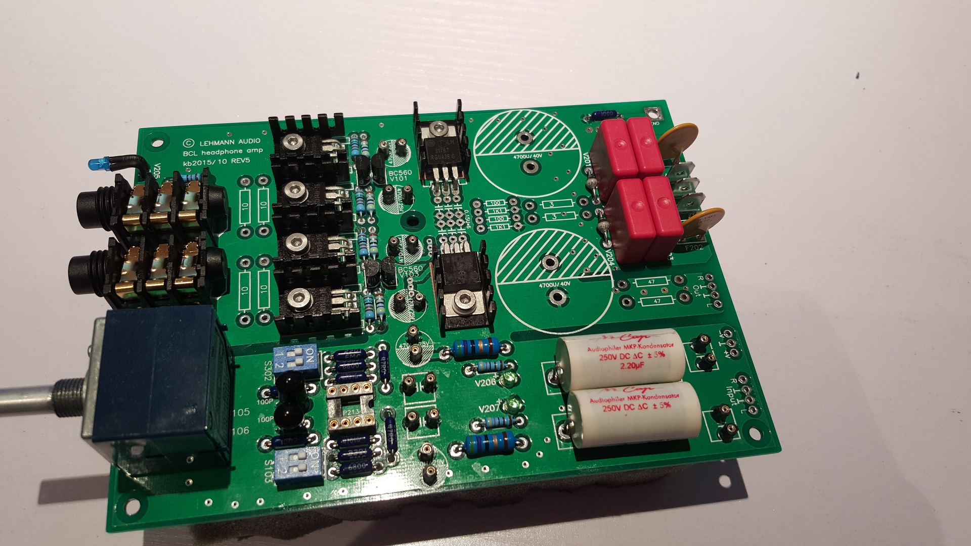
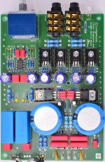
Regarding my own progress:
I've finished the base build! I use most original Lehmann parts and from there on I will test different parts and combinations in the sockets I've installed. I also still got some RA resistors incoming for the signal outputs.
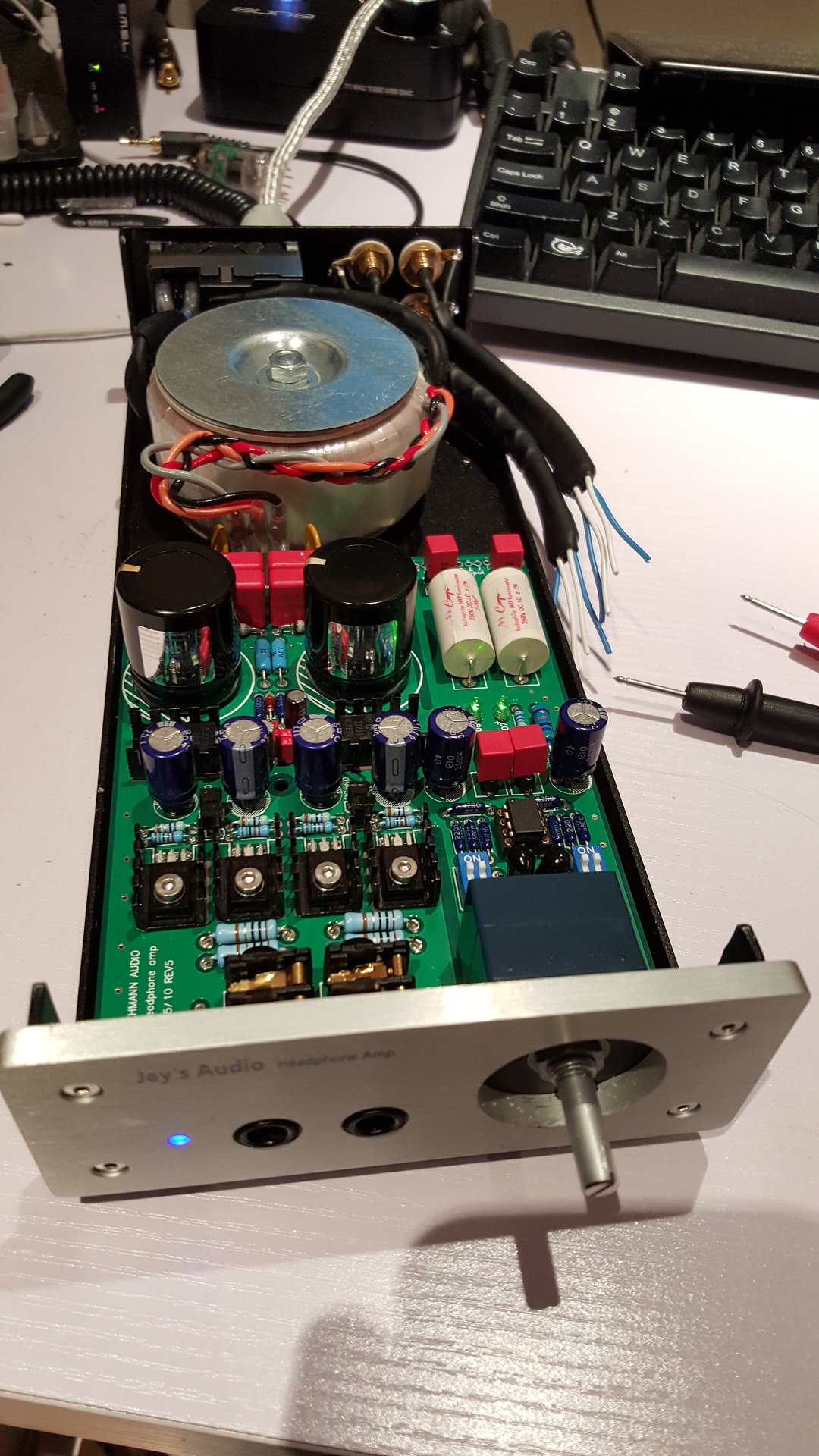
First smoke test went fine. Turned it on with the standard OPA2134AP. good DC offset and parts didn't get to hot.
Then I dropped in my dual discrete OPA111VMs. DC offset = PERFECT!
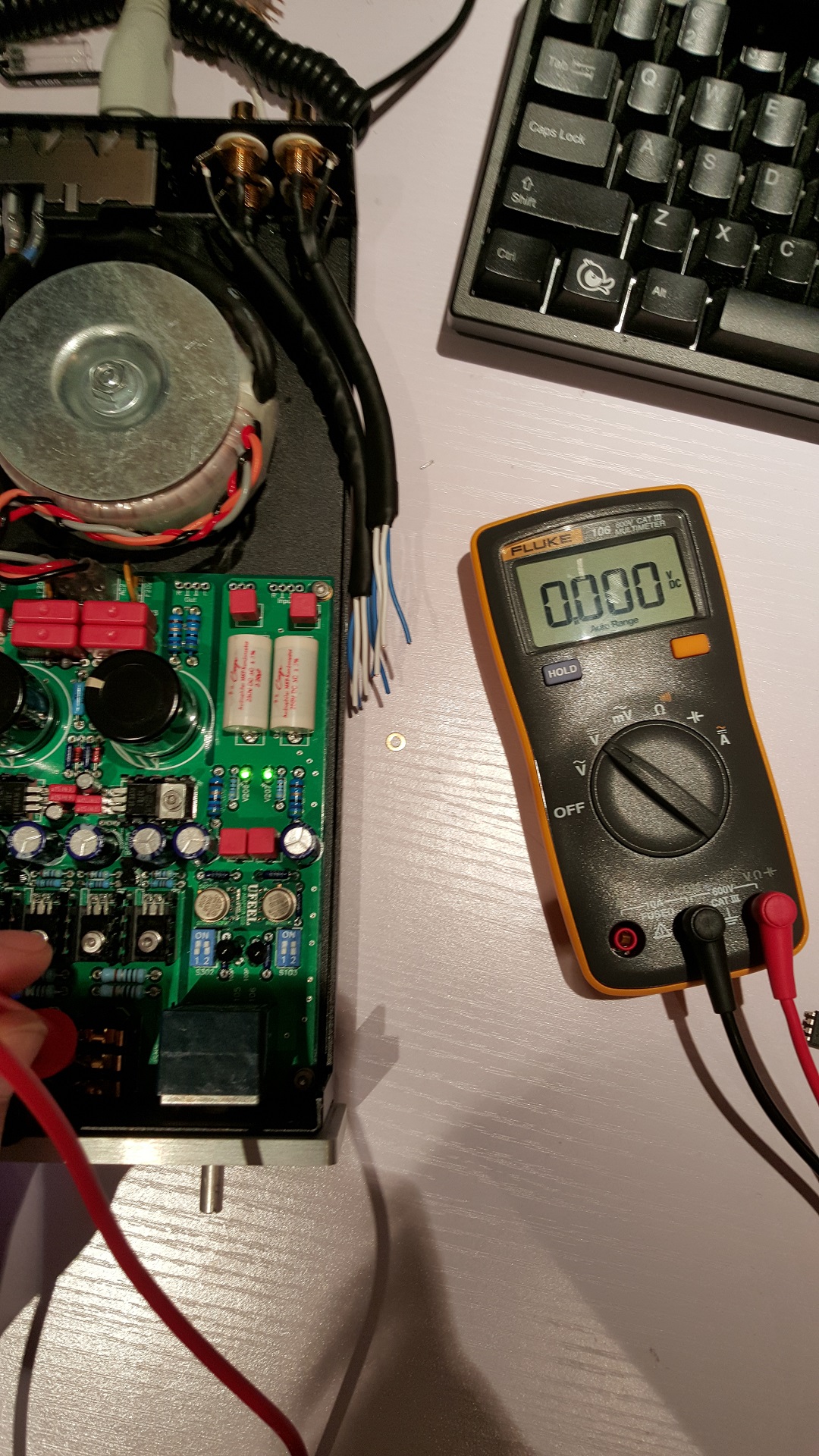
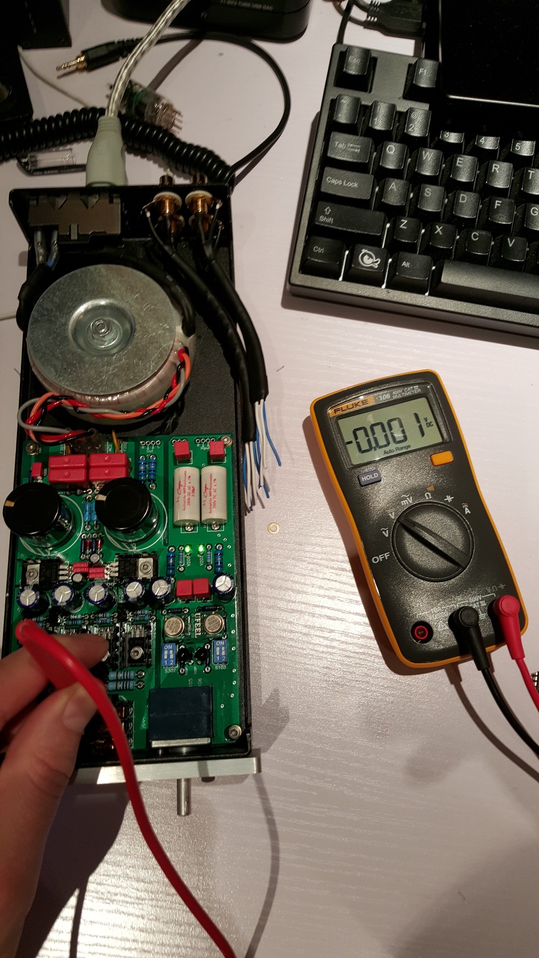
Tried all other opamps and got no big excesses in DC offset.
Next step is to give the device some burn in time. Then solder the signal cables in and do some testing with some inexpensive IEMs and rechecking DC offset after a while.
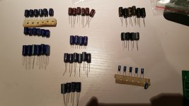
Then the fun can begin! The parts testing. I've got a good collection of caps to test for the device.
PSU output:
Nippon LXZ 470uf 25V (standard, they seem legit)
Nippon LXZ 470uf 35V (different colors and different batches)
Nippon LXZ 560uf 35V (same series as the 470uf 25V)
Nippon KZM 470uf 35V (same specs as Panasonic FR)
Panasonic FC 470uf 25V (good old trusted FC)
Panasonic FM 470uf 35V (near same specs as Nippon LXZ)
Panasonic FR 470uf 35V (some like em some don't, i've had good experiences with them)
For opamp:
Elna Silmic II 470uf 25V (black/gold)
Elna Silmic II 100uf 35V (black/gold)
Panasonic Pureism 470uf 25V (audio grade)
Panasonic Pureism 220uf 25V (audio grade)
Nippon ASF 470uf 50V (audio grade capacitor used in high-end brands)
Nippon ASF 470uf 25V (audio grade capacitor used in high-end brands)
Nippon AWJ 220uf 25V (REALLY big for their capacity and power rating. Like Silmic. Considered High-end audio capacitor by Nippon. From their catalog the best I could find.)
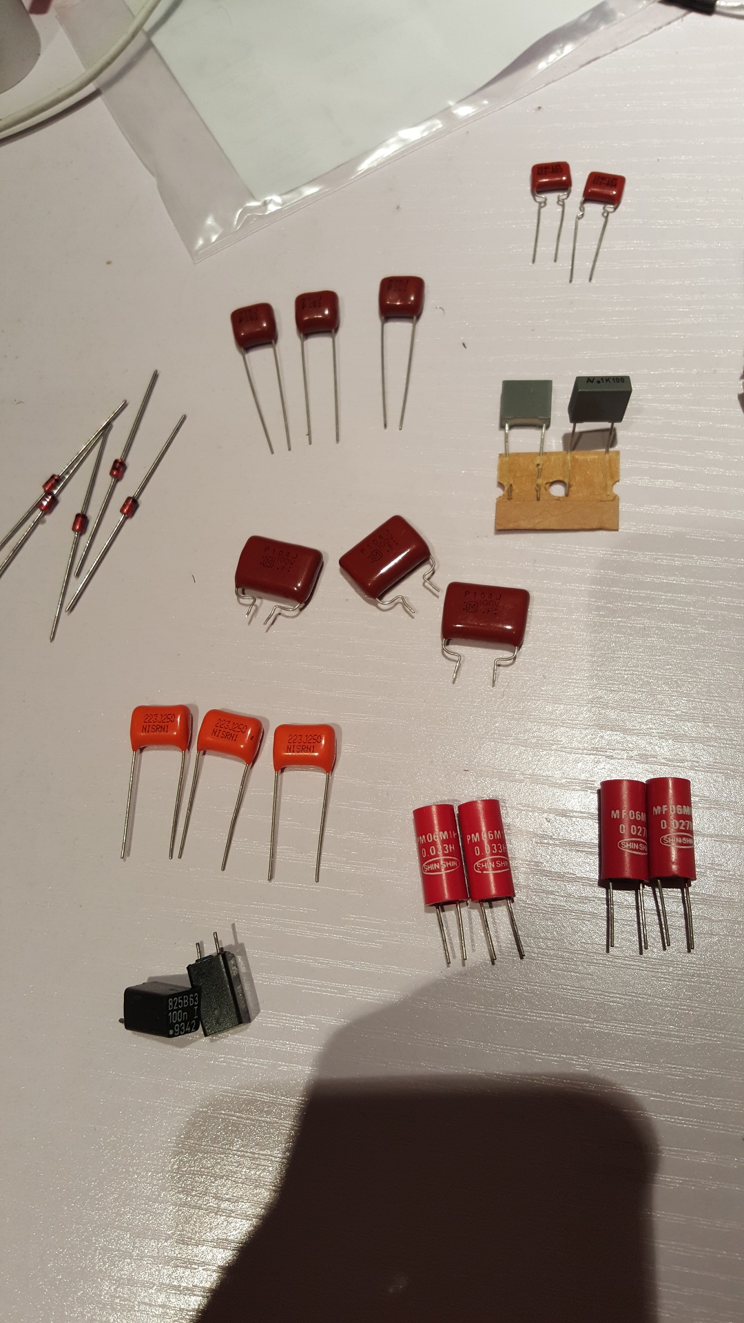
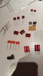
For the input bypass and opamp coupling positions:
Wima FKP4 0.022uf MKP
Shin Shin 0.027uf 50V Polystyrene
Shin Shin 0.033uf 50V Polystyrene
NIS 0.1uF 100nK 125vac MKP
NIS 0.022uF (22nJ) 250v MKP
AV R84 0.1uF 100v MKP
SOSHIN LCR825 0.1uf(100n) 63v MKP
ECQ-P 0.027uF (273J) 50v MKP
ECQ-P 0.1uF (104J) 100v MKP
Will be interesting to see how these influence the sound. I will change them at after all other capacitors.
And after that I have some RA 1W resistors to swap the Vishay MBEM0414s out. To see if this improves anything.
Not to be disrespectful but I already see you use a lot of inferior parts that I definitely would not have chosen and your way of connecting the signal cables is also definitely not preferable to soldering them in place. (I tried something like this with halved dip8 sockets of high quality and this was already problematic in terms of a solid connection. Your solution is even less solid with the pc fan connector.)
If I am not mistake I see Panasonic FC caps near the opamp? They are not well suited for this position. I found them to be empty and hollow against the Panasonic Pureisms and Elna Silmics in this position. FCs will be good at the PSU output though but even there are better choices to be made than the FCs for just the same money.
I am very interesting what end result you will achieve. What is your goal with this project?
I personally would advise you to not just use parts you still have lying around but select better parts for your project that are well suited for their function. The orignal Lehmann is a highly tuned device. And most of the parts are chosen with care for a good overal result. Just putting in random parts in won't get you near that same quality.
Just my honest opinion. Not meant to criticize your work whatsoever. Just a different point of view into DIY projects.
Regarding my own progress:
I've finished the base build! I use most original Lehmann parts and from there on I will test different parts and combinations in the sockets I've installed. I also still got some RA resistors incoming for the signal outputs.
First smoke test went fine. Turned it on with the standard OPA2134AP. good DC offset and parts didn't get to hot.
Then I dropped in my dual discrete OPA111VMs. DC offset = PERFECT!
Tried all other opamps and got no big excesses in DC offset.
Next step is to give the device some burn in time. Then solder the signal cables in and do some testing with some inexpensive IEMs and rechecking DC offset after a while.
Then the fun can begin! The parts testing. I've got a good collection of caps to test for the device.
PSU output:
Nippon LXZ 470uf 25V (standard, they seem legit)
Nippon LXZ 470uf 35V (different colors and different batches)
Nippon LXZ 560uf 35V (same series as the 470uf 25V)
Nippon KZM 470uf 35V (same specs as Panasonic FR)
Panasonic FC 470uf 25V (good old trusted FC)
Panasonic FM 470uf 35V (near same specs as Nippon LXZ)
Panasonic FR 470uf 35V (some like em some don't, i've had good experiences with them)
For opamp:
Elna Silmic II 470uf 25V (black/gold)
Elna Silmic II 100uf 35V (black/gold)
Panasonic Pureism 470uf 25V (audio grade)
Panasonic Pureism 220uf 25V (audio grade)
Nippon ASF 470uf 50V (audio grade capacitor used in high-end brands)
Nippon ASF 470uf 25V (audio grade capacitor used in high-end brands)
Nippon AWJ 220uf 25V (REALLY big for their capacity and power rating. Like Silmic. Considered High-end audio capacitor by Nippon. From their catalog the best I could find.)
For the input bypass and opamp coupling positions:
Wima FKP4 0.022uf MKP
Shin Shin 0.027uf 50V Polystyrene
Shin Shin 0.033uf 50V Polystyrene
NIS 0.1uF 100nK 125vac MKP
NIS 0.022uF (22nJ) 250v MKP
AV R84 0.1uF 100v MKP
SOSHIN LCR825 0.1uf(100n) 63v MKP
ECQ-P 0.027uF (273J) 50v MKP
ECQ-P 0.1uF (104J) 100v MKP
Will be interesting to see how these influence the sound. I will change them at after all other capacitors.
And after that I have some RA 1W resistors to swap the Vishay MBEM0414s out. To see if this improves anything.
Attachments


This not going to be my main headamp.
This is why I don't see the need to spend alot of money on it.
Signal cable connections are for ease of use as it will be tested against a few other designs, and I'll use the same enclosure.
The one that gets to stay will have ałl connections soldered.
The other designs are:
AD797+BUF634
AD797+CCS diamond buffer
2sk170 stage+CCS diamond buffer.
Ah ok. I get it. It's always nice to have a headamp on the side. Why not focus on one project at a time? I think the quality will be way higher. Unless you are doing it for third parties of course for profit within a time limit.
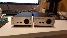
I've got the device up and running.
Impressions so far:
Good solid built! Still deciding on caps. PSU caps don't differ a lot except for the Panasonic FRs. They seem to be thinner but wider. I prefer a more natural sound. So I will probably stick with the Nippon LXZs.
I tried different caps as bypass caps with the input caps ranging from 0.022uf to 0.1uf.. NO! I also tried without them.. guess what.. NO difference. What will be the damage if I would remove them? Lehmann did it with the SE with the high-end mundorf input caps like I have..
Haven't decided on the opamp coupling caps yet. Right now I'm in favor of some smaller 47uf Elna Silmic IIs that still need to run in. So if they are already good now they will only get better. The Panasonic Pureisms seem to be a bit more detaild and wider. But I've noticed they get worse after burn in somehow.. Also got the Nippon audio caps left but the need to be soldered since their legs are to thick to fit in the sockets. I am thinking to try the 220uf AWJs.
The best improvement I got from changing the little caps in between the bigger opamp coupling caps. I run with the 0.033uf Shin Shins. They are really opening things up. Lifting some kind of veil.
When rolling opamps I am in favor of the OPA111VM with my Aune T1 tube DAC and the OPA627BP with my internal ESS Sabre ES9018K2M DAC (Which is actually more pleasant than the Aune T1, which is a bit harsh but more detailed.) Also tried the Sanskrit. Missing rythm and order. Its a good sounding device but the sound is messy and tiring.
I will keep swapping parts and testing untill I find the best combinations.
After rolling some opamps I've also decided to build of buy a better DAC because these sources won't cut it anymore. The BCL can do more. It's super tight and I feel it has loads of headroom for my cans.
Last edited:
Removed all the caps at the red Wima FKP4 positions.. no change! Like the real Lehmann BCL SE.. I think Lehmann also found out they were not doing anything.. Maybe these positions were still in the PCB design from earlier versions with different parts choices.. The Mundorf MKP caps I use are really good anyway. Connected to Aune T1
Last edited:
Ah ok. I get it. It's always nice to have a headamp on the side. Why not focus on one project at a time? I think the quality will be way higher. Unless you are doing it for third parties of course for profit within a time limit.
I've got the device up and running.
Impressions so far:
Good solid built! Still deciding on caps. PSU caps don't differ a lot except for the Panasonic FRs. They seem to be thinner but wider. I prefer a more natural sound. So I will probably stick with the Nippon LXZs.
I tried different caps as bypass caps with the input caps ranging from 0.022uf to 0.1uf.. NO! I also tried without them.. guess what.. NO difference. What will be the damage if I would remove them? Lehmann did it with the SE with the high-end mundorf input caps like I have..
Haven't decided on the opamp coupling caps yet. Right now I'm in favor of some smaller 47uf Elna Silmic IIs that still need to run in. So if they are already good now they will only get better. The Panasonic Pureisms seem to be a bit more detaild and wider. But I've noticed they get worse after burn in somehow.. Also got the Nippon audio caps left but the need to be soldered since their legs are to thick to fit in the sockets. I am thinking to try the 220uf AWJs.
The best improvement I got from changing the little caps in between the bigger opamp coupling caps. I run with the 0.033uf Shin Shins. They are really opening things up. Lifting some kind of veil.
When rolling opamps I am in favor of the OPA111VM with my Aune T1 tube DAC and the OPA627BP with my internal ESS Sabre ES9018K2M DAC (Which is actually more pleasant than the Aune T1, which is a bit harsh but more detailed.) Also tried the Sanskrit. Missing rythm and order. Its a good sounding device but the sound is messy and tiring.
I will keep swapping parts and testing untill I find the best combinations.
After rolling some opamps I've also decided to build of buy a better DAC because these sources won't cut it anymore. The BCL can do more. It's super tight and I feel it has loads of headroom for my cans.
Hi,
I always have a few projects going, either in design stage, parts collection stage or parts collection and build stage.
My main project now though is a modular DAC.
I work on headamps etc to either take a break from the DAC project or when I'm stuck while waiting for parts.
I also consider populating bought PCB's a bit of relaxation as most my projects are build on perf board and require alot more from me to get them right.
Headamps, once they're all done and I've listened to them enough to really pick the one that suits me best, I'll sell of the others.
Have you guys matched your BJT's?
I think I have enough of all types required to get decent matches for all of them. That should make for a more stable circuit, less offset and the option to bias the transistors higher with enough heatsinking.
I always match EVERYTHING that I can. I order like 10 times more parts and measure everything and make pairs. Also for future projects. Got really good results by doing that.
BC560s and BC550s are all matched, also matched the BD139-16s and BD140-16s. I make sure I use the best parts newly available. Used fairchild for the transistors and ON for the voltage regulators. I also got extra voltage regulators. In case there would be a big imbalance. I haven't had any problems with these puppies. Specs seem quite tight.
The resistors I use are military grade. They barely need matching but I still match them. You see my result above. Practically 0mv dc offset. Sound is really clean and stable.
With this circuit you can build a 'very good sounding' headamp with fairly cheep parts. It will sound better than most other headamps that are much more expensive.. but if you really take care of the components selection process and do some modification I think you will not need another amp after that anymore except if you want selectable inputs for example.
The thing I run in to with this amp are the limitations of my sources haha. It really brings forward their limitations now and I will be looking into making a new DAC
Last edited:
- Status
- This old topic is closed. If you want to reopen this topic, contact a moderator using the "Report Post" button.
- Home
- Amplifiers
- Headphone Systems
- [Headamp] upgrading a Lehmann BCL clone