what do you think about this design?
Hi Sam
You want me to miniaturize this too?
")
No more money for new parts. My wife is paying me every month on 15th
It is a bit too complicated for me (your attached circuit I mean, not the situation with my wife
 )
) Thank you, nevertheless.
I finished the second channel of the AN-222 Fig.4 circuit (1.5 hours this one).
Spent some time on measurements too. I will post them later.
Best Regards
George
George and all
The DL103 goes very well with the following circuit.
amplifiers
You could even use the LM394 although it is a bit old
and maybe no longer available. Use MAT02 instead
or paired transistors.
Supply with two rechargable batteries that are charged
when the amplifier is switched-off.
nonik
The DL103 goes very well with the following circuit.
amplifiers
You could even use the LM394 although it is a bit old
and maybe no longer available. Use MAT02 instead
or paired transistors.
Supply with two rechargable batteries that are charged
when the amplifier is switched-off.
nonik
Hi nonik
What you suggest is what sam suggested to me in #14 and in #22 posts.
But thanks for the confirmation of positive outcome from Hiraga pre-pre.
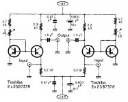
Actually I am aware of 2 Hiraga circuits, one using npn and the other pnp transistors, as in the attachments.
What transistors have you used to build it?
Best Regards
George
What you suggest is what sam suggested to me in #14 and in #22 posts.
But thanks for the confirmation of positive outcome from Hiraga pre-pre.
Actually I am aware of 2 Hiraga circuits, one using npn and the other pnp transistors, as in the attachments.
What transistors have you used to build it?
Best Regards
George
Attachments
Last edited:


Hello all
Well, the choise of transistors can make a big difference, not only in noise but
also in characteristic due to the impedance that the MC-cartridge will see.
Thisa will infuence the roll-off at high frequencies.
My friend Laurent did build it with LM394 indeed but we also used the 2SC1775
that Hiraga proposed in his original publication in l'audiophile.
Supply does not have to be so high. the + and - 6V as in the original schematics
are fine. Remember, the ouput-signal is to be fed into an RIAA pre-amp.
So output will be around 5mV ( 50mV max )
You do need an output cap however but as it, due to the high input impedance
of the RIAA stage, can have a rather moderate value, you have plenty of choise
in good caps to choose from.
The schematic proposed in the beginning of this threat needed an electrolytic.
So to the choise of transistors and caps: let your ears be the judge.
We found the 2SC1775 to be very pleasant while the LM394 sounded "harsch"
This is the set of Laurent about 15 years ago
On the bottom of the cabinet is the charger for the pre-pre.
speakers
nonik
speakers
Hello again
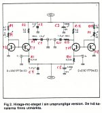
I took another look at the schematic of the Hiraga pre-pre
It is beautiful due to its simplicity.
The one transistor, connected as a diode will provide the
Vbe threshold that will bias the second transistor to have
exactly 0V potential at its emitter wich is the cirquits input
in de common-base configuration.
Using the same transistor or even better a dual (one chip)
will make this configuration temperature independant.
Still there could be a little offset ( that will create a small
DC current through your MC cartridge ) that can be nulled
using the trimmer in the collector of the first transistor.
Therefore, without cartridge connected, measure input to
ground and adjust for absolutely zero.
The 390Ohm resistor in series with the output is, in my
opinion not necessary because the circuit has no feedback
and therefore no risk of oscillation when charged with a
capacitive load ( longer cable ) because that is what these
series resistors are used for.
When you are sure, the input of your RIAA pre-amp is
capacitor coupled, you could ommit the output cap.
especially in this configuration I would pay attention to the
order of switching on and off your equipment or have it
automated.
I would implement a dummy-resistor between negative supply
and ground. Value chosen so that from both supplies the
same current is drawn.
This to avoid that one supply battery is loaded double
according to the other which could unbalance supply voltages
when the batteries are losing their full charge.
nonik
btw masag1
The schematic you show ( symmetrical pre-pre ) is mine.
It was a thought scribbled to paper quickly to remember.
Hans has put it on his website wich is ok for me.
We did prototype it but it appeared to be unstable in
terms of DC drift.
So I do not recommend building it.
nonik
The schematic you show ( symmetrical pre-pre ) is mine.
It was a thought scribbled to paper quickly to remember.
Hans has put it on his website wich is ok for me.
We did prototype it but it appeared to be unstable in
terms of DC drift.
So I do not recommend building it.
nonik
Hi all
Nonik thank you for the Hiraga pre transistors information.
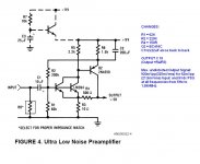
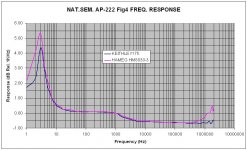
I finished the bench test of the miniaturized pre-pre of Nat. Sem. AN-222 Fig.4
Freq. Response measured manually (PS), just to see what happens outside from the 20Hz-20KHz window
The peak at 3Hz is with the 10uf input electr. Cap (C1). When I changed it to a 1uF MKT the peak shifted at 9Hz.
The value of Input Resistor (R8) does not change the Freq. Response at all. What it changes is the input signal amplitude. For Signal Source=50R:
R8 =1200R> Output = 0dB
R8 = 470R> Output = -0.34dB
R8 = 200R> Output = -1.40dB
R8 = 100R> Output = -2.97dB
R8 = 47R> Output = -5.70dB
Please remember that all the above hold true for a bench freq. Generator as the signal source. When the signal source is the MC cartridge, few things may change.
DC at Input.
No DC at Input (due to the capacitor C1).
But during turn-on, a DC pulse appear at input.
When input is loaded with 1200R this DC pulse is 42mV.
When 50R is placed in parallel with the 1200R (to simulate the cartridge) the DC pulse measured across the 50R is 2mV. This corresponds to a current of 40uA through the cartridge.
Output DC Offset
There is a DC present at the output. For 9Vdc PSU, this offset is 618mVdc. I placed a 1uf MKT at the output and Rload=47000R. This cap and Rload were in place when the freq Response was measured.
Circuit seems very stable electrically. Power was supplied from a variable output stabilized bench PSU through a 1 m long cable.
When a X1 probe was placed at the circuit output, some 5MHz oscillation appeared on the output at high input signal level. This didn’t happen with a X10 probe.
I placed a 2uF MKT where the PSU cable entered the circuit and the problem was rectified.
Circuit starts to function from 3Vdc and up (lower PSU voltage, lower current draw, also smaller headroom).
What is next, is the real test, i.e. DL103.
Regards
George
(PS) Set-up: Hameg HM8030-3 function generator (50R output impedance), oscilloscope HM 203-7 (DC coupled , probes 150MHz, x10) and Keithley 175 true rms in dB mode
Nonik thank you for the Hiraga pre transistors information.
I finished the bench test of the miniaturized pre-pre of Nat. Sem. AN-222 Fig.4
Freq. Response measured manually (PS), just to see what happens outside from the 20Hz-20KHz window
The peak at 3Hz is with the 10uf input electr. Cap (C1). When I changed it to a 1uF MKT the peak shifted at 9Hz.
The value of Input Resistor (R8) does not change the Freq. Response at all. What it changes is the input signal amplitude. For Signal Source=50R:
R8 =1200R> Output = 0dB
R8 = 470R> Output = -0.34dB
R8 = 200R> Output = -1.40dB
R8 = 100R> Output = -2.97dB
R8 = 47R> Output = -5.70dB
Please remember that all the above hold true for a bench freq. Generator as the signal source. When the signal source is the MC cartridge, few things may change.
DC at Input.
No DC at Input (due to the capacitor C1).
But during turn-on, a DC pulse appear at input.
When input is loaded with 1200R this DC pulse is 42mV.
When 50R is placed in parallel with the 1200R (to simulate the cartridge) the DC pulse measured across the 50R is 2mV. This corresponds to a current of 40uA through the cartridge.
Output DC Offset
There is a DC present at the output. For 9Vdc PSU, this offset is 618mVdc. I placed a 1uf MKT at the output and Rload=47000R. This cap and Rload were in place when the freq Response was measured.
Circuit seems very stable electrically. Power was supplied from a variable output stabilized bench PSU through a 1 m long cable.
When a X1 probe was placed at the circuit output, some 5MHz oscillation appeared on the output at high input signal level. This didn’t happen with a X10 probe.
I placed a 2uF MKT where the PSU cable entered the circuit and the problem was rectified.
Circuit starts to function from 3Vdc and up (lower PSU voltage, lower current draw, also smaller headroom).
What is next, is the real test, i.e. DL103.
Regards
George
(PS) Set-up: Hameg HM8030-3 function generator (50R output impedance), oscilloscope HM 203-7 (DC coupled , probes 150MHz, x10) and Keithley 175 true rms in dB mode
Attachments
Hi all
With the mm cartridges, there seems to be a consensus that they are treated as voltage output devices.
With the mc cartridges (I am a newbe to this) there are two schools of thought:
One is that it is a voltage output device.
The other is that it is a current output device.
The published specs for the DL 103 are:
Output: 0.3mV
Resistance:40R
Inductance:?
So I would appreciate is someone could explain if –and why- the head preamplifier for the DL 103 should be:
1) V/V
2) I/V
(I think that I should not consider the I/I and V/I options, or should’t I ?)
tiefbassuebertr, thank you for your last answer.
Best Regards
George
Hi George,
Coil Inductance: 56µH
Best
Merlin El Mago
............. and protection of the moving coils against DC.Hello George
can you settle down the DC offset with a negative voltage instead of the ground?
Maybe using a small relay at the input to connect the cartrige after the voltage peak appears. Regards
Joao
I think, you mean symetrical voltage supply and thus a possibility of a DC coupling between moving coil cartridge and the input of the head amp (i. e. to avoid the serial capacitor).
Is my estimate right?
Then you need top class relais like post #26 about
http://www.diyaudio.com/forums/solid-state/153935-best-audio-relays-3.html
Last edited:
............. and protection of the moving coils against DC.
I think, you mean symetrical voltage supply and thus a possibility of a DC coupling between moving coil cartridge and the input of the head amp (i. e. to avoid the serial capacitor).
Is my estimate right?
Then you need top class relais like post #26 about
http://www.diyaudio.com/forums/solid-state/153935-best-audio-relays-3.html
Correct, I mean sym., and adjustable, voltage supply. As well the relay should have a time delay to switch / connect the cartridge after the circuit settles and runs in it's operating conditions- and of course, the relays should be top class, but this is preconditioned.
Hi all
I would like to build a MC head preamplifier for a Denon DL-103 cartridge.
A lot of tube schematics on the web and many with discrete semiconductors also to choose from.
During the search ,I had a look at AN-222 Fig.4 http://www.national.com/an/AN/AN-222.pdf
Specifications look fantastic, ease of building/ space/ cost all very good.
I would like to ask the participants of this forum if anyone has built it, any opinions and any possible drawbacks of this implementation. Best Regards George
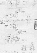
At botton my simulation results of Fig. 4 Page 4 National Semiconductor Application Note 222 July 1979 together with parasitic inductivity and serial resistance of DL-103 so as appropriate load capacitance.
Because I haven't p-spice model of LM 394, I use 2 normal small signal NPN BjT's
Please note the text advices by schematic and ignore the second schematic of SL-459 clone (simulation results aren't better than this one).
At next step I will try to transfere this circuit in such a version like that one of the moving coil head amp from Threshold SL-10 about
http://www.diyaudio.com/forums/pass-labs/151645-threshold-sl-10-a.html
especially for very low output voltage and very low input resistance like "MySonic Labs" - go to post # 10 about
http://www.diyaudio.com/forums/anal...-much-error-voltage-before-coil-damaging.html
1) schematic (all measurings by 15mVss output voltage)
2) Fourier Analysis lin 10 KHz (THD) K2: 20uV, K3: 4mV
3) Fourier Analysis log 10 KHz (THD, values are to enhance at 38 db because 15mV ~ -38db)
4) AC Analysis with appropriate input load
5) AC Analysis with inappropriate input load (e. g. R8=5K, definitely to avoid)
6) AC analysis ideal input generator instead of DL103
(i. e. without serial moving coil induction)
Attachments
Last edited:
Hi all
Merlin El Mago
Thank you for the info. It was one of the unanswered questions of that post.
In fact I measured it yesterday. The LCR meter - measures at 1028Hz, square wave 4Vpp- showed 46uH
Tiefbassuebertr
You are really very kind providing all this info and help.
First, It is through your post that I learned about the Threshold SL-10. Please go ahead.
Then it is your simulation of the circuit I am working on (AN-222 Fig.4).
Yes, this darn thing started oscillating (at 8 MHz) today morning on the bench as soon as I connected 1m (160pF) shielded cable at it’s input. I thought of the R8 as well, I placed a multiturn 1K trimmer, but to no veil, no matter how low I set it (OK, below 20R oscillation dies, hand in hand with the disappearing input signal).
Tiefbassuebertr, in my opinion at your simulation, it is a limited range of R8 values that causes this problem, because the feedback resistor (R4) is 500R, so the feedback is low. In my circuit, R4 is 150R, so the feedback is higher, thus, circuit is more prone to instability.
Nevertheless, I was determined to listen to the DL103 TODAY, so I picked up the bits and pieces, brought them upstairs together with the brand new DL103 in it’s box. I installed it on an old Kenwood deck, set it up, wired it to the oscillating head amp , then to the Hagermann Bugle…. And baaangggg
No. No bang.
Just a light continuous whispering noise from the speakers, but friends, the DL was singing.
Record after record, comparison after comparison with the other deck equipped with the Shure M97, the Denon seemed to me more (much more) dynamic, more “bodied”, really better sounding compared to the M97.
Then back to the bench. I thought of remedying the oscillation with a cap across R4 (feedback resistor).
A 390pF (ceramic. Did I hear Oh God! ?) killed it.
Good. I did the same to the other channel.
Each one tested alone. All clear.
New detailed measurements. After filtering, the –3dB roll off is at 1.8MHz.
Then, both channels tested together, side by side, fed from the same signal source, supplied from the same PSU.
F*&#@!!!!
It was 21:00, I was tired, looking at the oscilloscope screen showing the beautiful 8MHz sinusoid and standing a foot away from a set of hammers.
I said let it live one more night.
Now I came back home after some family transportation duties, and I said people have to know that this thing is a mistreater.
Tomorrow, I will not hammer it early on.
I will increase the capacitance across the R4 and IF it will behave, it will survive.
Or if you have to advise me for some other sort of cure.
Regards
George
Merlin El Mago
Thank you for the info. It was one of the unanswered questions of that post.
In fact I measured it yesterday. The LCR meter - measures at 1028Hz, square wave 4Vpp- showed 46uH
Tiefbassuebertr
You are really very kind providing all this info and help.
First, It is through your post that I learned about the Threshold SL-10. Please go ahead.
Then it is your simulation of the circuit I am working on (AN-222 Fig.4).
Yes, this darn thing started oscillating (at 8 MHz) today morning on the bench as soon as I connected 1m (160pF) shielded cable at it’s input. I thought of the R8 as well, I placed a multiturn 1K trimmer, but to no veil, no matter how low I set it (OK, below 20R oscillation dies, hand in hand with the disappearing input signal).
Tiefbassuebertr, in my opinion at your simulation, it is a limited range of R8 values that causes this problem, because the feedback resistor (R4) is 500R, so the feedback is low. In my circuit, R4 is 150R, so the feedback is higher, thus, circuit is more prone to instability.
Nevertheless, I was determined to listen to the DL103 TODAY, so I picked up the bits and pieces, brought them upstairs together with the brand new DL103 in it’s box. I installed it on an old Kenwood deck, set it up, wired it to the oscillating head amp , then to the Hagermann Bugle…. And baaangggg
No. No bang.
Just a light continuous whispering noise from the speakers, but friends, the DL was singing.
Record after record, comparison after comparison with the other deck equipped with the Shure M97, the Denon seemed to me more (much more) dynamic, more “bodied”, really better sounding compared to the M97.
Then back to the bench. I thought of remedying the oscillation with a cap across R4 (feedback resistor).
A 390pF (ceramic. Did I hear Oh God! ?
) killed it. Good. I did the same to the other channel.
Each one tested alone. All clear.
New detailed measurements. After filtering, the –3dB roll off is at 1.8MHz.
Then, both channels tested together, side by side, fed from the same signal source, supplied from the same PSU.
F*&#@!!!!
It was 21:00, I was tired, looking at the oscilloscope screen showing the beautiful 8MHz sinusoid and standing a foot away from a set of hammers.
I said let it live one more night.
Now I came back home after some family transportation duties, and I said people have to know that this thing is a mistreater.
Tomorrow, I will not hammer it early on.
I will increase the capacitance across the R4 and IF it will behave, it will survive.
Or if you have to advise me for some other sort of cure.
Regards
George
- Status
- This old topic is closed. If you want to reopen this topic, contact a moderator using the "Report Post" button.
- Home
- Source & Line
- Analogue Source
- Head Pre for Denon DL 103