Show me the actual measurements that support this "huge difference".
I did the same, and actually showed the measurements here, ages ago, when discussing the use of the same "waveguides", in a TH. A search on this forum might even bring them up.
The result? Absolutely no difference at all at bass frequencies.
If the dimensions of the waveguide are small compared to the waves that they're supposed to guide, they will have no effect.
A 100 Hz wave is over 340 cm long. If you go by 1/4 wavelength as a guide, the waveguide will still need to be 85x85 cm to start making any difference at all at 100 Hz. Have fun trying to fit something that size into a Tl's vent. They might make more sense in large FLHs or RLHs.
My position? If you want to make a few dB difference at midrange frequencies at the possible expense of lower bass extension from a TL box designed for bass duty - go ahead and use waveguides in it
If your measurements are at the same distance they won`t show much difference.
But go back like 2m or 3 or more then you might notice the spl is much higher far away compared to the enclosure with no flares at all.
This is due to improved air coupling.
Maybe there is a misunderstanding somewhere.
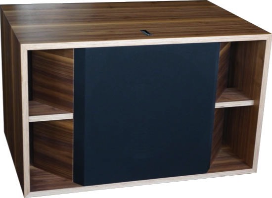
I am talking about something like this:
Now why would they complicate the design unnecessarily?
Maybe because it works.
If your measurements are at the same distance they won`t show much difference.
But go back like 2m or 3 or more then you might notice the spl is much higher far away compared to the enclosure with no flares at all.
I'd really like to see the theory that supports something like that. AFAIK the only way that I know to affect the change in SPL when measuring at difference distances from a source is if the effective size of the source is changed.
I am talking about something like this:
Now why would they complicate the design unnecessarily?
Maybe because it works.
That's not a waveguide. That's a flared vent, and yes they will make a difference at higher SPL levels as particle velocity and therefore turbulence are reduced at the end of the vent. At lower SPL levels the difference will be less noticeable (and measurable).
The "waveguides" I'm referring to are the 45 degree angled sections that some builders install along and inside the vent.
And BTW, some builders do "complicate their design unnecessarily". I'm a crappy box-builder, so I try not to do that
") . I don't incorporate anything in my designs unless they suit an audible and measurable purpose.
. I don't incorporate anything in my designs unless they suit an audible and measurable purpose.
Last edited:
My measurements agree...
Bob Brines also did the same measures and found no difference. I nly put them in when i need the bracing.
dave
That's not a waveguide. That's a flared vent, and yes they will make a difference
Scott uses them all the time in his designs... the latest a horn-loaded vent on a DBR for the Cube Magus 8.
dave
Brian, is it possible for you to post a Hornresp comparison (SPL/Displacement) of your POC6 against an standard vent box for the same driver? I'm curious to see the advantages.
The "transmission line" at your POC6 looks too short, so maybe you just changed the simulation and the port shape to calculate as TL, but the result could still be more close to standard vent. I could also be wrong due to me restricted knowledge.
Well, it is a 48 Hz (slightly lossy) MLTL, so it was going to be short any way you look at it
. When I did the vented box comparison, the output at the low end was similar (the MLTL's response was slightly better, if I remember correctly). The offset MLTL sim approach however allowed me to make sure that the 100 Hz ~ 200 Hz region was as smooth as possible, extending the usable passband of the build. A vented box with a vent this size and length will likely feature response aberrations in this region, the location and effect of these aberrations being somewhat unpredictable unless the sim program does a good job of matching the build's actual topology. And of course that extra internal panel does brace and reinforce the box somewhat
. All in all, for the cost of an extra panel in the box, I think it's a better approach.
The forum is called "T Line Bassheads Forum."
In the SPL world, there seems to be a ton of interest in transmission lines in the last couple years. I've noticed this on the Steve Meade forum too, and when I go to SPL shows.
I'm pretty active on Steve Meade's forum.
The way most T-lines are designed in the car audio SPL world just about kills me. "make the t-line area equal to Sd, make the length equal to the 1/4 wavelength of the driver's Fs. Put the driver at the closed end". That's all they do. I've tried to help people by simulating stuff for them in HornResp. I rarely get much traction.
Interesting.
I know a lot of people don't want to learn Hornresp.
One thing that I've found works fairly consistently, is to tune a transmission line to the same frequency as a vented box with the same driver, and make it the same volume.
IE, if you're vented box calculator says you need a two cubic foot box that's tuned to 30hz, you can use the same criteria for a tline and wind up with a response curve that's almost identical. This is because of Hoffman's Iron Law, of course.
One thing that I've found works fairly consistently, is to tune a transmission line to the same frequency as a vented box with the same driver, and make it the same volume.
Yup, and no matter how much you manipulate the taper, when you adjust to get a flat response, the total box volume tends to be that of a vented alignment using the same driver.
The main advantage of a using a TL for subwoofer duty is not just getting a slightly lower F3 (the large vent does help in getting this, particularly at higher SPL levels as there is less vent compression). It also provides a means of manipulating the impact of vent resonances to extend the passband of a box that has such a large vent. And advantage that's basically given away if you use the "classical" approach of locating the driver right at the start of the line.
I'm pretty active on Steve Meade's forum.
The way most T-lines are designed in the car audio SPL world just about kills me. "make the t-line area equal to Sd, make the length equal to the 1/4 wavelength of the driver's Fs. Put the driver at the closed end".
That design can result in a fairly large peak at the lower end of the passband. Perhaps the car audio crowd likes this
.That design can result in a fairly large peak at the lower end of the passband. Perhaps the car audio crowd likes this
I suspect you are correct in regards to the peak.
It also often greatly reduces the mechanical power handling of the sub, but most of these folks don't seem very concerned about that.
- Status
- This old topic is closed. If you want to reopen this topic, contact a moderator using the "Report Post" button.
- Home
- Loudspeakers
- Subwoofers
- He Did The Math