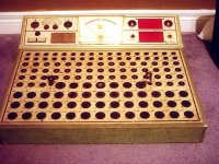
have you seen this tester?
I picked up this tester but dont have the coresponding chart or manual to figure out which tube to test in any of 131 sockets.. heh.
does anyone know anything about it?
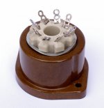
its a "TestMaster" with a logo that appeards to be an E with an M attached to it.
I picked up this tester but dont have the coresponding chart or manual to figure out which tube to test in any of 131 sockets.. heh.
does anyone know anything about it?
its a "TestMaster" with a logo that appeards to be an E with an M attached to it.
An externally hosted image should be here but it was not working when we last tested it.
")
Absolutely. I've taken cracking photographs in Toronto at this time of year out in the snow. I took all sorts of valve sockets etc out and fiddled about with different lenses until I got the best result. I wore a thick woolly pully and avoided kneeling in the snow. The first rule of good photography is loads of light. Here's an example (taken on two foot of snow and a bit of paper).
Attachments
Smak,
I did some googling for ya; can't find smack... diddly... uh... anything.
But you know, this ain't rocket science. I imagine when you get inside you could measure around a bit. Probabl;y a cascade of B+ voltages, plate resitors, heaters and all. You could make up a chart of what each socket represented.
Pretty frustrating when you realize there had to be THOUSANDS of those things around. I swear I used that very model as teen...
Good luck!
BTW, I did get a strange hit at tubedepot.com... might be worth an email to them?
Hell, we found a manual for anatech's 70 year old scope!
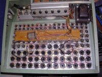
Crack that bad boy open... maybe ther is more info inside.
I did some googling for ya; can't find smack... diddly... uh... anything.
But you know, this ain't rocket science. I imagine when you get inside you could measure around a bit. Probabl;y a cascade of B+ voltages, plate resitors, heaters and all. You could make up a chart of what each socket represented.
Pretty frustrating when you realize there had to be THOUSANDS of those things around. I swear I used that very model as teen...
Good luck!
BTW, I did get a strange hit at tubedepot.com... might be worth an email to them?
Hell, we found a manual for anatech's 70 year old scope!
Crack that bad boy open... maybe ther is more info inside.
In the 1960's almost every corner store had a tube tester with a cabinet full of tubes underneath. They were basic emission testers with many different sockets. The idea was that they could be operated by anyone without a lot of thinking. The charts were simple, just told you which socket, and maybe what filament voltage. People actually fixed their own TV sets. Most 60's TV's ate tubes often, so you could often fix one with a tube tester.
Your tester looks like one of these. I am not sure but the logo might be Elmenco.
Your tester looks like one of these. I am not sure but the logo might be Elmenco.
Those labels appeared about the same time that the glowing glass thingies dissapeared. I worked in a TV repair shop when the RCA XL100 solid state TV came out. When the shop owner tried to fix it it smoked, a lot. He went out of business within a couple of years.
I crossed over to the dark side (SS repair) and got a job running the service department of a stereo store. We still had one of those tube testers in the corner, and sold Westinghouse tubes.
I crossed over to the dark side (SS repair) and got a job running the service department of a stereo store. We still had one of those tube testers in the corner, and sold Westinghouse tubes.
the plot thickens
hope that meeting works out for you Chris.. good luck and thnx for posting those shots.
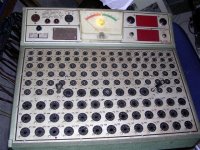
if you like my tester, some of the email queries i sent last night (thanks again poob) came back today.. there used to be something called a UTEST thats very similar.
check it out
still no roll chart though.. maybe i'll ask retroaudiolab for the number of sockets and if its 132 also then find some very-used tubes on that method.
oh and ec i'll get more pics for you later today.
hope that meeting works out for you Chris.. good luck and thnx for posting those shots.
if you like my tester, some of the email queries i sent last night (thanks again poob) came back today.. there used to be something called a UTEST thats very similar.
check it out
An externally hosted image should be here but it was not working when we last tested it.
still no roll chart though.. maybe i'll ask retroaudiolab for the number of sockets and if its 132 also then find some very-used tubes on that method.
oh and ec i'll get more pics for you later today.
- Status
- This old topic is closed. If you want to reopen this topic, contact a moderator using the "Report Post" button.
- Home
- Amplifiers
- Tubes / Valves
- Have you seen this tester?