They were ordered by a company that builds professional computers.
They needed 50 volt types, but the designer made an error with the surge values.
The guy i got them from worked at the company, he had something in the order of 100 of those boxes in his garage.
Overhere those caps were like $50-$60 the piece.
I got them for $ 4.25
Here in Holland no private person can get his hands on Mallory caps that size.
Such a story makes me raise my eyebrows, the money they wasted.
And the thought of the money i could have made on Ebay if i had bought all 100 makes me faint.
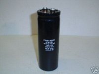
These are the caps I bought. My memory wasn't as good as I thought. I paid $52+shipping. Still, dirt cheap compared to what I've spent on others.
I still have 17 of these that I hope to use along the way. Popped two of them the first time I tried to use them. I didn't know which side was + and hooked them up backward. Fortunatey I was using my variac so they popped at low voltage. I've heard these things can really explode.
Why do I always have to learn everything the hard way?
You might want to check that guy's other auctions. He carries a lot of caps.
Blessings, Terry
Big caps,
http://cgi.ebay.com/ws/eBayISAPI.dll?ViewItem&category=36336&item=3850476823
2" Diameter
5 1/8" HeIght
$31.00
http://cgi.ebay.com/ws/eBayISAPI.dll?ViewItem&category=36336&item=3850476823
2" Diameter
5 1/8" HeIght
$31.00
Attachments
acenovelty said:Big caps,
Looks like rhose caps came out of the bowels of a Philips Gyroscan.....one of those huge torus looking machines used for body scans....
richj
capacitor
I got those caps today. Not much as far as markings g nly say 380lx 9020 cde usa 80 wv . but + and - are marked well , o on body and + and minus on terminals. They are 35mm X 60mm and 12000uf.It was same guy terry got those 15000uf from.So I guess they should be okay .they are alot smaller then the mallory ones I have but are 1/10 th the price. I stil hear bass well its the 2000hz - 4000 hz I am lacking in . Thats the freq of the turbine engines give off I think . They call it aviators ear.The saying with helicopters is , if you dont see it leaking hydraulic fluid dont fly in it , it must be empty.
I got those caps today. Not much as far as markings g
nly say 380lx 9020 cde usa 80 wv . but + and - are marked well , o on body and + and minus on terminals. They are 35mm X 60mm and 12000uf.It was same guy terry got those 15000uf from.So I guess they should be okay .they are alot smaller then the mallory ones I have but are 1/10 th the price. I stil hear bass well its the 2000hz - 4000 hz I am lacking in . Thats the freq of the turbine engines give off I think . They call it aviators ear.The saying with helicopters is , if you dont see it leaking hydraulic fluid dont fly in it , it must be empty.big giant caps
maybe when we got to the doctor we can get them to throw in a couple of those big caps with tests .They should have some spares in the repair department.I mean its already over 1000 bucks for an MRI so whats another 75.I think they have part time jobs in repair at our hosipital back home , they could pay me in caps.
maybe when we got to the doctor we can get them to throw in a couple of those big caps with tests .They should have some spares in the repair department.I mean its already over 1000 bucks for an MRI so whats another 75.I think they have part time jobs in repair at our hosipital back home , they could pay me in caps.
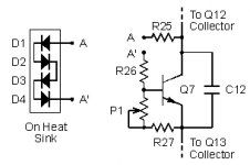
Could one of you who know the Leach design, explain the purpose for mounting the diodes D1-D4 through the heatsink? Does the heat cause them to change they values or something? How snug do they need to be? The bit I used was just a tiny bit larger than the diodes. They don't wobble around but they aren't snug either. Do they need to be?
Thanks, Terry
Thanks, Terry
As BJTs heat up, they tend to conduct more for a given bias. This causes more heat, causing more conduction and so on ending in smoking transistors without thermal compensation.
The voltage drop across the diodes decreases with temperature. Since they are in the upper leg of the Vbe multilier, the bias is reduced as they heat up, compensating for the output's tendency to run away with fixed bias.
The voltage drop across the diodes decreases with temperature. Since they are in the upper leg of the Vbe multilier, the bias is reduced as they heat up, compensating for the output's tendency to run away with fixed bias.
lateral mosfets don't have this problem. Vertical mosfets do to a lesser degree than bjts. At some high current vertical mosfets temperature coeficient goes negative, meaning that the runaway tendency is reversed.
Yes all diodes have a voltage drop. It usually decreases with temperature, but as you figured out, your rectifiers should have some heat sinking.
Yes all diodes have a voltage drop. It usually decreases with temperature, but as you figured out, your rectifiers should have some heat sinking.
Hi Terry,
The Prof. says about this:
The VBE Multiplier Bias Circuit
The collector bias currents in Q12 and Q13 flow through the VBE multiplier circuit shown in Figure 10. Q7 is connected as a dc voltage regulator employing shunt-series negative feedback. The dc voltage across Q7 is adjusted with P1 to set the bias currents in the output stage. D1 through D4 are mounted in holes in the heat sink with the output transistors to provide negative thermal feedback to the VBE multiplier. The diodes cause the voltage across Q7 to decrease as the heat sink temperature increases to prevent thermal runaway in the output transistors. C12 improves the voltage regulation across Q7 at high frequencies. In addition, it prevents any oscillations that might occur because of the shunt-series feedback around Q7.
Many amplifiers have the VBE multiplier transistor on the heat sink with the output transistors. This eliminates the need for the diodes. The wires which run from the circuit board to the transistor exhibit capacitance to ground which can affect the high-frequency response of the second stage. At worst, this could cause oscillation problems. With the diodes on the heat sink, resistors on the circuit board can be used in series with the wires to isolate this capacitance from the second stage. These resistors are R25 and R26 in Figure 10. If Q7 were mounted on the heat sink, isolation resistors could not be used because they would affect the voltage regulation between the collectors of Q8 and Q9.
No point in me paraphrasing it.
Prosit
Attachments
- Status
- This old topic is closed. If you want to reopen this topic, contact a moderator using the "Report Post" button.
- Home
- Amplifiers
- Solid State
- Have transformer, will build