You got it.
And so will others reading this thread.
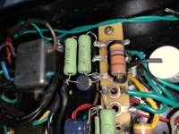
2 individual self bias networks, instead of a shared bias network.
Double the resistance for each individual cathode.
Bypass capacitor for each cathode.
This is even more important for a push pull amplifier, it helps to balance the 2 plate currents. Push pull output transformers work better with balanced quiescent plate currents.
K so I did one side. Now for the other. Since this is a stereo amp.
I had originally bought only 4 resistors...
But I need 8 for the 2 channels.
It’s 2 tubes per side in parallel.
You got it.
And so will others reading this thread.
2 individual self bias networks, instead of a shared bias network.
Double the resistance for each individual cathode.
Bypass capacitor for each cathode.
This is even more important for a push pull amplifier, it helps to balance the 2 plate currents. Push pull output transformers work better with balanced quiescent plate currents.
Hi thx
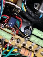
Also I had some Kiwame 270 Ohm 5W resistors already so I used those.. is it ok? Instead of 2W..?
I’m assuming yes cuz it’s more...
They are a little big though.. lol
Attachments
Higher wattage resistors have more surface area, so they run cooler when the power dissipated in them is the same.
Example:
1 Watt into a 2 watt resistor runs hotter, than 1 Watt into a 5 Watt resistor.
The difference is the cost of the resistor, and the additional space and weight that the 5 Watt resistor takes.
Example:
1 Watt into a 2 watt resistor runs hotter, than 1 Watt into a 5 Watt resistor.
The difference is the cost of the resistor, and the additional space and weight that the 5 Watt resistor takes.
An SRPP stage generally has the same voltage across the plate to cathode of both triodes.
But, a cascode works properly when the top tube's cathode impedance is low, and the plate impedance of the bottom tube is high.
Cascode amplifiers were quite common in RF and Radar circuits.
By biasing the top tube in the cascode with little or no bias, it has less plate to cathode voltage across it.
And that tends to reduce the top tubes cathode impedance.
Personally, I do not care for cascode stages in audio amplifiers.
And Personally, I do not care for SRPP in audio amplifiers.
Just my personal preferences.
I may have confused the issue of using a larger wattage resistor.
When the power dissipation is equal in a 2 watt resistor and in a 5 watt resistor, the 5 watt will be cooler (more surface area).
But . . . for the same watts dissipated, the Total heat energy that goes into the air is exactly the same.
Last edited:
Hi, so this amp is a SRPP.?? I was under the impression it’s single ended parallel.
2 tubes in parallel per channel.
Ok so it’s still fine for the 5w vs the 2w
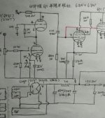
for the cascode part. To add resistor and cap to the top cascode of the 6SN7, to make the voltage across both triodes the same.
still not sure where to add the second resistor and cap... pin 8? To ground ? And cap across?
But there is the filament wires
on pins 7 & 8...
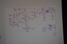
See my schematic
Thx
2 tubes in parallel per channel.
Ok so it’s still fine for the 5w vs the 2w
for the cascode part. To add resistor and cap to the top cascode of the 6SN7, to make the voltage across both triodes the same.
still not sure where to add the second resistor and cap... pin 8? To ground ? And cap across?
But there is the filament wires
on pins 7 & 8...
See my schematic
Thx
Attachments
While 7+8 is the heater its good practice to connect one of those pins to ground. Helps with noise reduction.
There are other ways to connect to like a splitter resistor network across 7+8 with centre tap to ground or to an elevated DC voltage.
I usually raise mine to about 40 volts.
There are other ways to connect to like a splitter resistor network across 7+8 with centre tap to ground or to an elevated DC voltage.
I usually raise mine to about 40 volts.
maddmaxxdrummer,
Your Input Stage is Cascode.
It is not SRPP.
Both Cascode and SRPP have the two tubes DC currents stacked in series.
Since it is a Cascode stage, do not put a resistor in the top triode's cathode.
Your Single Ended (SE) output stage is Parallel Single Ended (PSE).
Look through my Post # 65 again.
Single Ended is what you have.
Push Pull (PP) has 2 outputs that are in opposite phase (two tubes, an output transformer with a center tapped primary, and the out of phase plates go to the opposite ends of the center tapped primary.
Parafeed is usually single ended, but parafeed can also be push pull.
Lots of names for lots of topologies.
Last edited:
For the Cascode I was thinking more of an RF Cascode, not an Audio Cascode.
Yes, you can put a resistor in the top triode's cathode.
That will make the plate to cathode voltages the same, as you did say earlier.
That might, or might not, change the extreme high frequency performance.
But it might increase the dynamic range of the input stage (before it clips).
You will have to try it and see what the exact differences are in sound, and signal level before it gets to clipping.
What I do for the single ended amplifier input stage is quite simple.
I use an IXYS 900V current source, as the plate load for the input triode.
No need to elevate the input tubes filaments.
The IXYS IC only requires a current sense resistor, and a Gate stopper resistor.
That current source is connected between B+ and the input tube's plate.
I use simple RC coupling to the output stage grid(s), a cap from the input tube plate, and the other end of the cap to the junction of the grid resistor to ground and the grid stopper resistor of the output tube(s).
Simple.
Low Distortion.
Your schematics in Posts # 17, 45, 47, and 66 all have the input Cascode triode connections the same.
I am guessing that you like the Cascode circuit topology, better than other input circuit topologies.
If you want to make the plate to cathode voltages nearly the same, then . . .
Disconnect Pin 6 from Pin 2.
Connect a parallel network of 2.2k and 100uF between pin6 and pin2 (cap plus to pin6).
Connect the 1 Meg that Used to connect to Both pins 2 and 6, and connect it only to pin 2.
That will divide the plate to cathode voltages to be about the same on the two input triodes.
Try it and see if it works well for you.
Note: I can not see what the "fascination" nor the advantage is for using a pair of medium u triode tubes in Cascode circuit topology for audio amplifiers.
Perhaps an aggressive marketeer sold us a bill of goods.
Generally, the advantages of using a Cascode circuit at RF, goes completely away when used for Audio.
The RF Cascode circuits are used for very small signals, very low bandwidth circuits (bandwidth relative to the center frequency) and the signal voltages of the RF signals are very small.
Compared to the small RF voltages . . .
That small of an audio voltage is not nearly enough to drive an audio output stage.
Generally, using Cascode circuit to drive the output stage will have low dynamic range, high distortion, and depending on the high frequency load that the output stage presents, will result in high frequency roll off.
Parallel output tubes have 2x the Miller Effect capacitance, and can be just the thing that loads the Cascode too much at high frequencies.
With a single input triode, a resistive plate load, plenty of B+ voltage, and a self biased cathode with bypass cap, it is enough to drive a pair of parallel output tubes. Even without the IXYS current source as the plate load, the resistive plate load gave the gain, linearity, and voltage swing that is needed. The 6SN7 is a good example of a tube that works well there.
I remember a single 6SN7 triode that drove the famous Western Electric 212E triode. That 212E had 1250V on its plate.
That experience got me started designing and building vacuum tube amps again.
Just my opinions.
Sometimes simpler is better.
"You should make things as simple as possible, but no simpler" - Albert Einstein
Last edited:
Hi, ok but weren’t u saying I had to change the value of the original 2.2k to lower and the new one also ?
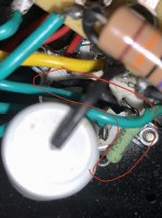
I see the 1Mohm I can just clip the connection between 2 and 6. Leave the 1Mohm in place which connects to pin 2 and 4 only after breaking connection to 6.
Then I can add the new resistor between 2 and 6 and bypass with the 100uf cap
Thing I don’t get is the original 2.2k/100uf network goes to pin 3 (green wire) then to ground... negative side of cap (brown wire connected there is ground)
So the new network does not need to return to ground ?
Sorry I’m not an expert in this...
Attachments
maddmaxxdrummer,
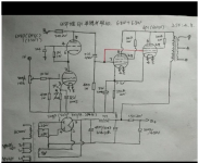
I have attached a very poor but accurate schematic.
If I remember, you were experiencing some strange sound (your recorded attachment).
It seemed that it might not just be bad connection, noisy part, but might be something on the verge of an oscillation.
So, I added four each 1k grid stopper resistors (actually, I just moved one of them that was already there, to its proper location, pin 1 . . .
With it wired Directly at the socket grid pin eyelet hole.
Keep all the ends of the 1k resistor wires short that connects to the socket grid eyelet.
Remember, for a grid stopper to work, you do not connect anything to the grids, except the grid stopper resistor (in this case 1k).
Attachments
Last edited:
Your input stage is Cascode. The B+ for it is split by the 30k plate load, top triode, 2.2k, bottom triode, and 2.2k to ground.
Reducing 2.2k will increase the current.
You can not stand any more current without changing the 30k, or raising B+.
Reducing 30k will reduce the signal voltage gain, and maximum signal swing.
Either
1. live with the original 30k, top triode, bottom triode, 2.2k,
2. live with 30k, top triode, 2.2k, bottom triode, 2.2k.
See if that works for you well.
3. or change the circuit so that it is no longer a cascode circuit.
A simple circuit with a plate load resistor (30k), 6SN7 triode, and 2.2k resistor could work very well. Or pick another triode.
Or, use an IXYS current source instead of the 30k plate load resistor. (6SN7 or another triode).
- Home
- Amplifiers
- Tubes / Valves
- Has anyone tried a "12AU7 to 6SN7 Adapter"?