the device output , in common drain ,
exhibit a exponential or power law , i didnt check exactly at this time ,
at level from 0 to 0.1V Vgs.
It's a power. The standard mosfet model in Spice doesn't have any provisions for modelling the subthreshold region.
The Renesas devices have only 1S transconductance. You need no less than 5 pairs to match the transconductance of a K1530/J201 verticals and about 10 pairs to match the typical transconductance of a IRFP240/9240 pair. It is unlikely you could use the Renesas laterals to feed 4 ohm loads, if you also consider the load impedance dips.
Edmond, I would be very glad to have any realistic models for FETS you know of, obsolete or not, and I ask you put them here or link to their source. The EXC10N16/10P16 models from Exicon have very smooth crossover behavior, so I thought they were faulty, but now I am not sure.
.MODEL ECX10N16 NMOS (LEVEL=1 VTO=-66.415M KP=20U L=2U W=76.3794M GAMMA=0 PHI=600M LAMBDA=3.44617M RD=244.181M RS=178.517M IS=10F CGSO=100P CGDO=100P TOX=0 NSUB=0 TPG=1 UO=600 KAPPA=200M RG=367.902 RDS=16.0012K )
.MODEL ECX10P16 PMOS (LEVEL=1 VTO=56.1959M KP=20U L=2U W=49.9039M GAMMA=0 PHI=600M LAMBDA=16.6941M RD=458.28M RS=214.674M CBD=1.00674N IS=10F CGSO=100P CGDO=100P TOX=0 NSUB=0 TPG=1 UO=600 KAPPA=200M RG=35.8793 RDS=1MEG )
It's a power. The standard mosfet model in Spice doesn't have any provisions for modelling the subthreshold region.
The Renesas devices have only 1S transconductance. You need no less than 5 pairs to match the transconductance of a K1530/J201 verticals and about 10 pairs to match the typical transconductance of a IRFP240/9240 pair. It is unlikely you could use the Renesas laterals to feed 4 ohm loads, if you also consider the load impedance dips.
The only real drawback is a little less power output
although with two to three pairs it became negligible.
I used three pairs of such devices , albeit in T03 casing ,
with 2 X 60V supply and loaded with 4R at full volume during
hours in heated stages , never they did fail in 15 years...
Anyway , here some food for brain on that matter.
The devices you re quoting are no better in real world....
http://www.ti.com/lit/an/snaa045/snaa045.pdf
Last edited:
Snaa045, Pages 16, 18 & 19 show the effect of the 4702 direct driving the Laterals vs the verticals. All benefit from an intermediate driver stage, to boost the HF frequency response. But note in the direct drive plots where 4702 output current is the limiting factor that the Lateral gives ~ one octave more HF bandwidth cf the the low Vgs 1530/201 with the 240 about half an octave narrower.
Can I assume this indicates that the Lateral's capacitance is easier to drive?
Can I assume this indicates that the Lateral's capacitance is easier to drive?
The only real drawback is a little less power output
although with two to three pairs it became negligible.
I used three pairs of such devices , albeit in T03 casing ,
with 2 X 60V supply and loaded with 4R at full volume during
hours in heated stages , never they did fail in 15 years...
"A little less power" is a matter of taste. 40W/8ohm as in the National Application Note is, in my opinion, not even close in providing the dynamics that digital recordings require.
Otherwise, it's not about reability (leteral devices are self-protecting, by quickly dropping the transconductance at high currents) but about quality. Three pairs of laterals driving 4 ohm resistive at 60V peak means 15A peak, or 5A peak per device. If you consider the real speaker load impedance dips, you are pushing the laterals at their maximum rating. They won't crash and burn, but the distortions close to clipping in such an amp must be increasing very fast to the audible limits. Do you have any measurements to show?
IMO, 3 pairs to drive 4 ohm of speaker load is not enough even for power bipolars, 4 pairs would be acceptable, 5 even better. But then, whatever makes you happy.
"A little less power" is a matter of taste. 40W/8ohm as in the National Application Note is, in my opinion, not even close in providing the dynamics that digital recordings require.
They made measurements up to 125W RMS/8R for Renesas laterals ;
there s also the THD graphs at 100W/8R.
Otherwise, it's not about reability (leteral devices are self-protecting, by quickly dropping the transconductance at high currents) but about quality. Three pairs of laterals driving 4 ohm resistive at 60V peak means 15A peak, or 5A peak per device. If you consider the real speaker load impedance dips, you are pushing the laterals at their maximum rating. They won't crash and burn, but the distortions close to clipping in such an amp must be increasing very fast to the audible limits. Do you have any measurements to show?
IMO, 3 pairs to drive 4 ohm of speaker load is not enough even for power bipolars, 4 pairs would be acceptable, 5 even better. But then, whatever makes you happy.
You must account for supply sag of a few volts and a few more for the
laterals losses but even then it s within specs of such devices.
Taking a 15A figure the max power dissipation is 225 W wich is easily
handled by three pairs that have a 600W total TDP.
As for measurements, i have none other than max output power
measured with simple voltmeter and resistive load , wich yielded
about 130W/8R and 200W/4R.
On a side note , laterals are way more rugged than bipolar devices
despite max currents that are a fraction of the latters , surely
due to hot spots being absent , a by product of their topology.
Speaker loads are a completely different story. I would not try to "sell" that amp as anything but 100W/8ohm (speaker load).
On a side note, you are otherwise incorrect. Hot spots are not absent, but the condition of activating them. In lateral mosfets, the transconductance decreases with the drain current (this is, BTW, a distortion mechanism, one more reason to get bad distortions while approaching Idmax), therefore the drain current is self-limiting. In bipolars the transconductance increases with the collector current, which in turn increases the collector current (for the same Vbe), etc... until a hot spot (around silicon defects) is overheating and the silicon is melting around. You probably mean the SOA of mosfet devices is larger than for bipolars, but this is true for both lateral and vertical mosfets.
On a side note, you are otherwise incorrect. Hot spots are not absent, but the condition of activating them.
You should read twice what you write.
If the necessary conditions are absent then the phenomenon
doesnt occur.
Besides , the app note above use these devices for a 100W amplifier,
wich is somewhat exagerated since two would be better suited.
Otherwise , it is obvious that you have very few if any practice
of theses devices elsewhere than in simulators and in general
theory books , yet you didnt notice that THD is on the same
level as way higher Gm devices.
Ok, you are right. I know very little about mosfets and bipolars, and I bow in front of your obvious superior knowledge of theoretical device physics and practical electronics design.
It's time to bed now, good night.
Last edited:
preference, fashion, marketing
To me they are very useful, as I just purchased a bunch of 2SJ201/2SK1530 pairs, enough for the rest of my life.
My preference for MOSFETs is based on the absence of 2nd breakdown and storage effects of minority carriers.
As a matter of fact, is started with bipolars, but finally I felt more comfortable with MOSFETs.
True, but I prefer more difficult and challenging ways. Something new.
Building (read: copying) a blameless BJT amp is just boring. In the past I've built enough of that kind stuff.
Unfortunately, they are now useless. That pair is dead and buried by the manufacturer (Toshiba).
To me they are very useful, as I just purchased a bunch of 2SJ201/2SK1530 pairs, enough for the rest of my life.
There is no winner. The ultimate distortion performance, in any realistic implementation, and for the same stability margins, are virtually identical. It's a matter of preference, fashion, marketing, etc...
My preference for MOSFETs is based on the absence of 2nd breakdown and storage effects of minority carriers.
As a simulating only designer, I am surprised you prefer mosfets.
As a matter of fact, is started with bipolars, but finally I felt more comfortable with MOSFETs.
Bipolar power device models are much better (and even much easier to improve, if one has the patience, passion and the right tools).
True, but I prefer more difficult and challenging ways. Something new.
Building (read: copying) a blameless BJT amp is just boring. In the past I've built enough of that kind stuff.
EKV models
Hi Keane,
You will find them here and here.
Notice that the syntax of these models has been adapted to MicroCap rules. For the LTspice syntax see Andy's models.
As long as one can buy these FETs, I wouldn't call the models 'obsolete'.
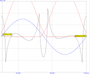
I'm sorry to say so, but they are simple level1 models, which don't support sub-threshold conduction. The picture below (black curve) shows the effect on the distortion residual. Around X-over you clearly see the large spikes, which shouldn't be there.
Cheers,
E.
Edmond, I would be very glad to have any realistic models for FETS you know of, obsolete or not, and I ask you put them here or link to their source.
Hi Keane,
You will find them here and here.
Notice that the syntax of these models has been adapted to MicroCap rules. For the LTspice syntax see Andy's models.
As long as one can buy these FETs, I wouldn't call the models 'obsolete'.
The EXC10N16/10P16 models from Exicon have very smooth crossover behavior, so I thought they were faulty, but now I am not sure.
[models]
I'm sorry to say so, but they are simple level1 models, which don't support sub-threshold conduction. The picture below (black curve) shows the effect on the distortion residual. Around X-over you clearly see the large spikes, which shouldn't be there.
Cheers,
E.
Attachments
I just purchased a bunch of 2SJ201/2SK1530 pairs, enough for the rest of my life.
Wow, so you are going to build something by yourself! I can wait for pictures and measurement results!
May I suggest also using 2SK389/2SJ109 for small signal? They are excellent matched pairs and you can still buy them.
loudspeaker impedance
Talking about loudspeaker impedance dips, I always thought that loudspeakers exhibit impedance peaks. So I wonder where did the worry about those 'dips' come from? Is it just nonsense from hearsay, or are there indeed speakers that dip below two ohms or so. If so, why those dips and how many of those 'rogue' speakers are there altogether around the world? Also, are they really high-end speakers or is it just ill designed crap, which should be ignored?
BTW, my speakers are 'dip free', so no need to build an amp for my own use that can handle 2 ohms.
Cheers,
E.
Wow, so you are going to build something by yourself! I can wait for pictures and measurement results!
Well, It's not the first time I'm going to build an amp by myself.
May I suggest also using 2SK389/2SJ109 for small signal? They are excellent matched pairs and you can still buy them.
Sure, that's an interesting option. Where I can buy these duals?
Ok, you are right. I know very little about mosfets and bipolars, and I bow in front of your obvious superior knowledge of theoretical device physics and practical electronics design.
I m afraid that you ll receive the same answer from the vast
majority of people that had to deal with those lateral fets.
Although troubling at first look , their lower Gm is not an issue
in power amplifiers , there s more parameters that must be taken
in account.
Higher transconductance of the bipolar would be an advantage
but then you have to look at their loading effect of the previous
stages , wich destroy their apparent advantage , as what is gained
in and end is lost in the other one.
This can be countered by using a triple EF but at the expense
of stability , or bandwith if the arrangement is to be compensated.
Hey, take a look at this electro-thermal modeling app note from Fairchild. I have been thinking about trying to make macro-models in SPICE for electro-thermal and more advanced models, but I would have to implement the entire model as equations and spice-sources and am not sure if it is too technical for me. This app note uses the VDMOS model.
http://www.fairchildsemi.com/an/AN/AN-7534.pdf
Actually I have already done some pseudo-modeling of realtime temperature of BJT's:
http://www.diyaudio.com/forums/solid-state/182554-thermaltrak-tmc-amp-2.html#post3009046
http://www.diyaudio.com/forums/solid-state/182554-thermaltrak-tmc-amp-2.html#post3009201
No dips in the impedance curve does not mean than current will never be higher than estimated for the lowest portion's equivalent resistance. Depending on woofer parameters, the maximum current can get as high as three times the DC current, with a specially trimmed waveform (which can easily appear when the amp is in voltage clipping during a too loud bass transient). In practice this can be reduced to 2x, or 2.5x to be really safe.BTW, my speakers are 'dip free', so no need to build an amp for my own use that can handle 2 ohms.
Current demand loudspeakers
See e.g.
AES preprint 2411 (Vanderkooy, John; Lipshitz, Stanley P.): Computing Peak Currents into Loudspeakers
This paper presents techniques and examples for computing the peak current that a complex loudspeaker load can draw when driven by a signal with well-defined voltage limits. This peak current can be characterized by a nominal resistance Rn. The theory for Rn of Preis and Schroeter, valid for infinite bandwidth, is applied to finite-bandwidth impedance data acquired from an FFT analyzer. Some theoretically calculable loads and their respective Rn values are presented. Simple test data are analyzed which show that the impedance data must be real at the band edge. Complexities involved in the processing are discussed and illustrated for real loudspeaker impedance measurements, and phase tilting or use of the cyclic minimum-phase impedance is necessary to provide consistent results. It is not unusual for the nominal resistance Rn of a loudspeaker to be less than half the minimum impedance value.
AES preprint 2293 (Otala, Matti; Huttunen, Pertti): Peak Current Requirement of Commercial Loudspeaker Systems
Measured terminal impedances of several commercial loudspeaker systems are developed into their equivalent electrical circuits by using the Brune network synthesis method. The synthesized circuits accurately describe the properties of the load as seen by the amplifier feeding the loudspeaker system. A group of non-sinusoidal audio signal sequences, which cause the loudspeaker system to draw momentary currents considerably in excess of what could be expected from the rated terminal impedance is identified using computerized network analysis methods. The maximum value of peak current of peak current reported for a commercial loudspeaker system is 6.6 times larger than that of an eight ohm resistor. The current peaks typically last a few hundred microseconds. The current peaks are caused by simultaneous parallel excitation of several of the drivers of a multiway system, by summation of cancellation currents originating from the energy stored in the mechanical and electrical reactances of the circuit, and by impedance transformation effects in the crossover network. The results imply that for short periods of time, an amplifier should be able to drive, with full output voltage swing and without appreciable distortion, loads equal to a resistor of one ohm.
AES preprint 1987 (Martikainen, Ilpo; Varla, Ari; Otala, Matti): Input Current Requirements of High-Quality Loudspeaker Systems
Based on an analysis of the equivalent circuit of a multiway loudspeaker, the possibility of large drive currents is predicted for a class of non-sinusoidal band and amplitude-limited signals. The current builds up as coherent sum of two parts; charging of the driver reactances, and simultaneous current drain by several drivers. The input current of three commercial loudspeaker systems was measured using a signal derived from on the analysis. The results show that a loudspeaker may draw currents three to six times larger than those calculable from the rated speaker impedance. This indicates that certain generally accepted power amplifier design criteria should be reconsidered.
Steven
Talking about loudspeaker impedance dips, I always thought that loudspeakers exhibit impedance peaks. So I wonder where did the worry about those 'dips' come from? Is it just nonsense from hearsay, or are there indeed speakers that dip below two ohms or so. If so, why those dips and how many of those 'rogue' speakers are there altogether around the world? Also, are they really high-end speakers or is it just ill designed crap, which should be ignored?
They indeed exist. The Wilson WATTs are notorious for that (down to 1.5 ohms or so in the midrange). I've also measured that sometimes with other speakers using questionable means to EQ out peaks in the frequency response, especially ones with so-called "minimalist" first order networks.
- Status
- This old topic is closed. If you want to reopen this topic, contact a moderator using the "Report Post" button.
- Home
- Amplifiers
- Solid State
- Has anyone seen this front-end before?