DarkOne said:Ilimzn, please discuss with x-pro and try to find out some right value. There is nothing wrong with at least 1V volage on R22, even if 65mV is enough for you. Yo simply can't go wrong with higher value. Please use 65mV bias if your amp has not enough harsh sound.
Well, then explain to us all here how you 'can't go wrong' with at least 1V, why not 10, or 30 then?
I can see that increasing the voltage drop there can be beneficial for the VAS stage because it will be very difficult to saturate on clipping, but you also lose that voltage drop off the rail, and your current mirror becomes a rather bad one.
Oh, and 65mV is not a 'bias' here, and weren't we talking about R18 and 19?
BECAUSE I CAN
you CAN also put 100 ohms there, or 1Mohm (not that it will work then, but indeed you CAN), so?
ilimzn said:
Well, then explain to us all here how you 'can't go wrong' with at least 1V, why not 10, or 30 then?
I can see that increasing the voltage drop there can be beneficial for the VAS stage because it will be very difficult to saturate on clipping, but you also lose that voltage drop off the rail, and your current mirror becomes a rather bad one.
Oh, and 65mV is not a 'bias' here, and weren't we talking about R18 and 19?
you CAN also put 100 ohms there, or 1Mohm (not that it will work then, but indeed you CAN), so?
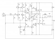
I'm still talking about voltage across R18, R19 and R22 (the voltage is almost the same)
You can use any resistor value you want, but I've pointed out some starting values. A my experience goes 1V is the minimum I recomend. When I used less amp began to sound harsh. You just have to choose some compromise between VAS stage linearity, current requirements and max. output voltage swing. If you choose lower voltage, you will get voltage swing nearly rail to rail, but the linearity is poor.
So, what do you want? Poor sound and power or good sound and less power?
One thing, that was evident on the first schemnatic - there was biasing problem between differential and VAS stage. Input stage had to do a lot of work to keep DC low and then it didn't have enough power to work with input signal.
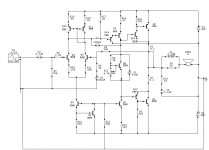
Schematic 2 complemetary pair
This is the second schematic aand it has a complementary pair in the output stage. I know already the emitter follower has lower TIM than the complimentary pair but to come back to my problem with harsh sound which seems to be linked with the LTP and the VAS which of the two will be better? Thanks
This is the second schematic aand it has a complementary pair in the output stage. I know already the emitter follower has lower TIM than the complimentary pair but to come back to my problem with harsh sound which seems to be linked with the LTP and the VAS which of the two will be better? Thanks
Attachments
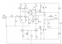
ilimzn said:R17 needs to be connected to emitter of Q4, not base...
I'm sure you meant Q14.
Cheers!
Re: Last mods
No, re-read my post again...
Cheers michael
zeus_threat said:Ok for the resistor on q14 so the previous schematic was right.
No, re-read my post again...
Cheers michael
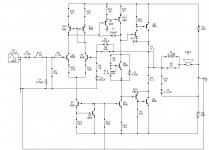
Correct schem
I think this is what you meant micheal, am i right? Plus the amp gets hot with no signal but when loaded with a source it cools down. There is a small buzz coming from the speaker for the first schematic i posted. In case its parasitic oscillation will C7 and C2 solve this problem? (Sorry but no scope under my reach for analysis)
I think this is what you meant micheal, am i right? Plus the amp gets hot with no signal but when loaded with a source it cools down. There is a small buzz coming from the speaker for the first schematic i posted. In case its parasitic oscillation will C7 and C2 solve this problem? (Sorry but no scope under my reach for analysis)
Attachments
C2 and C1 are fairly large-valued, that would slow down the amp quite a bit. If they have to be made that large to get the HF oscillations out, suspect grounding / pcb layout problems!
C7 - if you ground the input in your present amp, does the buzz disappear or not? If not, C7 will probably not help...
A lot of the performance of an amplifier is tied to the layout of the PCB...
C7 - if you ground the input in your present amp, does the buzz disappear or not? If not, C7 will probably not help...
A lot of the performance of an amplifier is tied to the layout of the PCB...
zeus_threat said:Hi, am a DIY but not an expert in amplifier design, I've built this amp but the highs are sounding harsh and bass is not sufficiently present. I have measured the output impedance to be 0.437 R, but stilll don't have anyy clue on how to smooth the high frequencies. Any help would be welcome. Thanks
Try removing C2. The first time I built a Leach amp it also sounded harsh. The culprit turned out to be the low-pass filter cap. It was a ceramic cap that sounded terrible.
(I haven't read the full thread, so I apologize if this post is redundant.)
C7, input filter: It is actually rather difficult to get a 220p ceramic cap that would not be near-ideal. Ceramics re VERY well behaved for these capacitances. I would suspect the input stage is reflecting a negative impedance to the input, this is not a trivial thing to solve (although a series resistance between the input filter and the base of the input Q often does it, but there are other repercussions). You already have a resostor there. You may want to try shorting C7 and checking if the 'buzzing' dissapears.
C2 and C1 are 'interactive' - it is not just enough to increase them or decrease them. For starters, I would try removing C2 (across the feedback resistor), or, placing a small value resistor (1-2.2k) in series with it. You may have the same negative input impedance problem for both sides of t he LTP.
Finally, CFPs can sometimes oscillate within their respective feedback loops, and rather nasty at that (like in the MHz region), compensation of the rest of the amp will not helpo this at all, and in fact, may make things worse in some cases.
To be perfectly honest, this may be impossible to debug 'long distance' - a few oscilograms would really help, also a view of the layout - one ground connected at the wrong point may make it oscilate and we'd be running in circles here tryng to figure out why.
- Status
- This old topic is closed. If you want to reopen this topic, contact a moderator using the "Report Post" button.
- Home
- Amplifiers
- Solid State
- Harsh sounding amp