I am all set up to run an input to the amp using a signal generator (400hz 100mV peak to peak square wave)? Typically I would use 500mV peak to peak if on solid state but somewhere I saw somebody testing guitar amps and that is where the 100mV came from?
I have already verified the signal (both A & B channel) to the grid of the tone tube. I have seen this term used so I assumed it meant the 12AXY right before the tone control circuitry?
I finished fab'ing a second 8ohm load and have installed a load on both channels. Oscope will be set to AC coupling and probe to plates (socket pins 1 &6, 175VDC). Scope is okay to 600V peak to peak. Scope probe set to 10X. With AC coupling on will the trace center itself? So I wont have to go off looking for it?
If probe is 10X will have to set scope vertical to something like 5mv or 2mV. In AC coupling mode is it necessary to have the probe set to 10X?
Discovered on V2 (12AX7) tube pin 1 (plate) channel A (nonworking channel) measuring 350V when it should be 150V. The opposite side pin 6 measures 150V. There is 340V being fed to the plates and 330K ohm resistors are supposed to drop it to the 150V. Interestingly measuring the resistors they measure the 330K. Can a resistor measure but be shorted when the high voltage is put to it?
Okay as everyone knows I I Am rough with the circuit Theory. Same voltage on both sides of a resistor could indicate no current flow through the plate load resistor. So I will look at the cathode circuit a little bit harder I did measure cathode voltage this morning and it measures 1 volt where it should be measuring 1.2 volts.
The plan was to prove out the chassis...output transformers, power supply, etc before investing more funds to acquire know good 12AX7 tubes and 12AU7 tube. Well I believe the time has come to start investing in those tubes.
Both channels are operating though Channel B is a bit weaker than Channel A. Doesn't have the same volume and bass response. I would throw a 10% decrease in volume significant bass response difference. Still sounds nice even at higher volume levels.
Purchased a matched set of 12AX7EH and 12AU7 tube/s from Dougs Tubes.
Last edited:
Got the new balanced Tung Sol 12AX7 tubes and the NOS phase splitter tube. Quickly learned the new tubes with straight leads are problematic with the old worn sockets. Lost channel B. Maybe the original tube I thought I was having problems with was just the socket. Will need to check. So tweaked the contact pins using small jewelers screwdriver. The tube did have a better fit when I was done. At the end of the exercise got both channels operating but still have some lost volume and bass on channel B.
Could a 2V difference in the cathode voltage cause this? Also still need to replace some of the old paper film electro caps. Only the cpling caps on the outputs got done.
Could a 2V difference in the cathode voltage cause this? Also still need to replace some of the old paper film electro caps. Only the cpling caps on the outputs got done.
Last edited:
Hi Bob,
Sorry, just saw the thread and your posts. Ever get the feeling you're just talking to yourself?")
You figured out a lot of stuff on your own, and that's pretty good. Keep in mind that with tube circuits, voltages are mostly approximate. The lower cathode voltage indicates that that tube isn't conducting as much current as the other. However, older resistors can easily be out 20% or more. Best to measure the resistors you are checking for voltage drops.
-Chris
Sorry, just saw the thread and your posts. Ever get the feeling you're just talking to yourself?
You figured out a lot of stuff on your own, and that's pretty good. Keep in mind that with tube circuits, voltages are mostly approximate. The lower cathode voltage indicates that that tube isn't conducting as much current as the other. However, older resistors can easily be out 20% or more. Best to measure the resistors you are checking for voltage drops.
-Chris
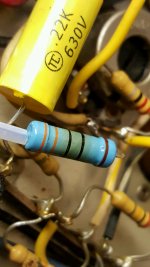
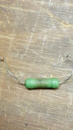
Chris replaced the output cathode 330 ohm 3W output catode resistor with metal film. You know that metal film is warm just by the smell of the coating cooking. Can't help but think the original green resistor is more robust?
Attachments
Hi Bob,
That resistor is already discoloured? Wow. There is supposed to be 106 mA running through it, meaning that you are dissipating 3.7 watts of heat. That should have been a 10 watt resistor. The old part is looking toasted pretty well also. What does the resistor in the other channel look like?
Normally a 3W resistor would be dissipating 1 to 1.5 watts maximum, so that would be about 18 volts across that resistor (1 watt). You're not far off from double that amount! I can't believe that they messed up that design so badly. It's even off from 1.5 watts (would be 22 volts in that case). Is there anywhere you can check to see if that 35 volts is really what they want there?
I normally use metal oxide resistors for high dissipation positions, and wire wound for anything 5 watts and higher.
-Chris
Playing with what appear to be 100 ohm cathode adjustment pots a piece of the resist layer came out of the channel B potentiometer. So now on Quest for a something to replace it with. I assume using these two pots will allow to balance the cathode voltages between each channel.
Last edited:
I got a little soft over the balance pots discovered a local electronic parts distributor one town over that deals in this type of stuff so I ordered 2 pieces of a lockable 100 ohm potentiometer two watts, sure that's more than whats needed. Very interested to see how much stuff this distributor carries so that I can minimize all of the shipping charges I've been accumulating on projects. Granted they didn't have these parts in stock but they ordered them from their distributor and they will be shipped with their weekly shipment of incoming product.
Will have to open the .200 inch holes that are in the chassis now to something closer to .375 inches to allow the adjuster on the pot to protrude through the chassis. Because the parts will now be accessible I thought it would be good to have a locking nut on the adjuster.
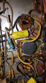
Also got the additional 4 pieces of .22 k ohm capacitor to continue on replacing the rest of the coupling capacitors.
Will have to open the .200 inch holes that are in the chassis now to something closer to .375 inches to allow the adjuster on the pot to protrude through the chassis. Because the parts will now be accessible I thought it would be good to have a locking nut on the adjuster.
Also got the additional 4 pieces of .22 k ohm capacitor to continue on replacing the rest of the coupling capacitors.
got the new 100 ohm potentiometers and replaced the channel B potentiometer. Will start to replace the balance of the old wax electrolytics. The first image shows the 3/8" adjust stem coming up through the chassis, inbetween the output tubes. This has the locking nut in the event that these adjusts do anything they can be locked so interested hands will not be able to change the setting.
Attachments
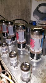
It appears that the 50ohm (there is a 100ohm resistor in parallel with the 100ohm potentiometer) adjustment capability of these balance potentiometers are to balance the current to the cathodes of a pair of the output tubes?
Each of the output tubes of each pair (channel A and channel B) have similar cathode currents based on measuring the voltage at the cathode pins. On this amp channel A cathodes measures 34.6V and 34.7V. Channel B cathodes measures 33.1V and 33.2V.
So one would assume the cathode current to be higher on the pair of channel A output tubes.
If the potentiometer on channel A is adjusted to increase the resistance the cathode current decreases and the voltage measurement at the cathode pin should decrease.
Is this how these potentiometers are to be adjusted?
Have several hours of listening.....WOW WOW incredible sound. Now a tube fan. Am finding myself thinking of being able to withdraw from the solid state campaign of building bigger and bigger and bigger solid state power systems. Thinking of reducing the collection of solid state components and doing another tube project, mono blocks. Playing this amp with a pair of OHM C2's. Will connect up to a pair of Klipsch Forte's out of interest. May also get the Snell EII's out of the closet....probably more interested in this than the Klipsh's.
Hi Bob,
Fantastic! You're now into the reason for building / restoring amplifiers.
Well, instead of chasing higher powered solid state amps, or any type of amplifier for that matter. concentrate on quality. That normally sets you in the 12 to 50 watt tube sets, or in the 25 watt to 200 watt solid state amps. Higher powered models sometimes force design decisions that takes the amplifier away from high fidelity. Not always, but nearly so.
-Chris
I recently was gifted a Harman Kardon A50K integrated that seems to be in pretty good shape, by that I mean it is very clean inside and there are no signs of any hack work being done, the outside cleaned up really well with a clean chassis it has all the preamp subes but I need to purchase power tubes I found some Electro- Harmonix 7591A tube at Upscale Audio near my house. I am not having great luck finding 7533's . What needs to be done to use the 7591A's ? Thanks
I used the 7591A tubes in my Eico ST70, and normally use Electroharmonix for design work and my servicing business.
I found a manual for an A500 that uses 7355 outputs. They are a beam power tube, the 7591A is a Pentode. So first blush, I would be looking at something like a 6L6GC, but more careful examination of the characteristics between them is required. First check heater current to rule tubes out that draw too much (over 800 mA). The plate is rated for 18 watts dissipation, so a 5881A is closer at 23 watts, but still a 900mA heater current draw.
The grids and cathode pins need to be rewired to use the 5881A or 6L6GC types, and the bias network may need to be adjusted for the proper current (cathode resistor values). The extra 400 mA heater current may or may not be okay depending on the transformer. Replacing the #47 lamps with LEDs may help a little bit.
Absolute minimum service will be to replace coupling caps, and I would change the filter caps for sure. Use CE manufacturing for those (www.tubesandmore.com). If you replace any resistors, don't use the old carbon composition types, but you must look at the voltage rating specs for new resistors! You cannot "cheap out" by leaving the original coupling caps, that may cost you output transformers, power transformers and output tubes.
-Chris
Thanks for the information , I will research the5881 and 6L6 family of tubes. Before anything else all the coupling caps will be changed out. as well as the PS caps, Do you have any style or brand suggestions for the coupling caps ? I have this gentlman (https://richardsonsusa.com/antique-radio-vintage-audio-repair-refurbishing/) I am working with to do the work on the amp. Resistors will be part of the service. Once he goes over it I will see what else may need replacing or that would be a good idea to replace as long as we are in there. Thank you for the heads up on the tubes, I obviously read something wrong while researching this amplifier. Thank you for the quick reply.I used the 7591A tubes in my Eico ST70, and normally use Electroharmonix for design work and my servicing business.
I found a manual for an A500 that uses 7355 outputs. They are a beam power tube, the 7591A is a Pentode. So first blush, I would be looking at something like a 6L6GC, but more careful examination of the characteristics between them is required. First check heater current to rule tubes out that draw too much (over 800 mA). The plate is rated for 18 watts dissipation, so a 5881A is closer at 23 watts, but still a 900mA heater current draw.
The grids and cathode pins need to be rewired to use the 5881A or 6L6GC types, and the bias network may need to be adjusted for the proper current (cathode resistor values). The extra 400 mA heater current may or may not be okay depending on the transformer. Replacing the #47 lamps with LEDs may help a little bit.
Absolute minimum service will be to replace coupling caps, and I would change the filter caps for sure. Use CE manufacturing for those (www.tubesandmore.com). If you replace any resistors, don't use the old carbon composition types, but you must look at the voltage rating specs for new resistors! You cannot "cheap out" by leaving the original coupling caps, that may cost you output transformers, power transformers and output tubes.
-Chris
- Home
- Amplifiers
- Tubes / Valves
- Harmon Kardon A50K project