I have some power transformers from Plitron, but they have poor regulation and let too much line noise through. I think that the only use for a toroid transformer would be for audio coupling and switching power supplies.
-Chris
Problematic toroids you have - do they have static screen between promary and secondary?
I use power toroid to feed my own amp (not Plitron, custom made), and see no problems at all. It is absolutely silent, and even after very long runtime, it is just slightly warm.
Chris,
The fact that toroids have good bandwidth makes them vulnerable to line noise. Try putting ferrite beads on the primary side close to the coil. Use beads large enough to loop a turn or 2 around. If that doesn't provide enough suppression, look into commercial EMI/RFI power inlet filters.
The fact that toroids have good bandwidth makes them vulnerable to line noise. Try putting ferrite beads on the primary side close to the coil. Use beads large enough to loop a turn or 2 around. If that doesn't provide enough suppression, look into commercial EMI/RFI power inlet filters.
Chris,
The fact that toroids have good bandwidth makes them vulnerable to line noise. Try putting ferrite beads on the primary side close to the coil. Use beads large enough to loop a turn or 2 around. If that doesn't provide enough suppression, look into commercial EMI/RFI power inlet filters.
Right. And you can also buy Plitron toroids with electrostatic and/or magnetic shields between primary and secondary, look here: Plitron Power Trafo Site
Hi Eli,
Yes. That is exactly my point. Adding an air gap would be helpful as well. My personal opinion is that a toroid is not well suited for mains to circuit interface. An EI core is not only resistance to effective DC offsets (air gaps), but has higher HF loses. The added benefit is that the core can be coupled to a heat sink type surface so it runs cooler. That is one thing I'd love to see with a toroid, some way to sink the heat out.
This is why I am willing to give a serious try with toroid output transformers. That seems to be suited for a toroid and not an EI core as much. I still would like air gap(s) and some way to draw the heat out of the core.
Hi LinuksGuru,
I wonder how much extra using thermally conductive potting compound would make these?
-Chris
Yes. That is exactly my point. Adding an air gap would be helpful as well. My personal opinion is that a toroid is not well suited for mains to circuit interface. An EI core is not only resistance to effective DC offsets (air gaps), but has higher HF loses. The added benefit is that the core can be coupled to a heat sink type surface so it runs cooler. That is one thing I'd love to see with a toroid, some way to sink the heat out.
Yes, that made them passable, and the inlet filters are something I often use due to all the switching supplies out there. RF contamination is fairly common as well in our area (Toronto and the "GTA"). The thing is that an EI core is less expensive and requires less intervention. The only positive (aside from marketing value) I can see is form factor. However a "C" core will achieve that goal.Use beads large enough to loop a turn or 2 around.
This is why I am willing to give a serious try with toroid output transformers. That seems to be suited for a toroid and not an EI core as much. I still would like air gap(s) and some way to draw the heat out of the core.
Hi LinuksGuru,
I would agree.Problematic toroids you have
Nope. I didn't order them. Electrostatic screens are something I see as standard equipment for AC mains transformers.- do they have static screen between promary and secondary?
I'm guessing you sized it properly - good going! But still, how warm is the core getting? It may take hours to be able to sense the actual core temperature.even after very long runtime, it is just slightly warm.
I wonder how much extra using thermally conductive potting compound would make these?
-Chris
Hi Jim,
Yes, and thank you. I'm bopping around on their site, and have been for a while. The transformers I have here do not fill me with confidence though. After working with these, I'm convinced that Hammond is the way to go for power transformers.
At this point in time, it's a comfort thing. I am not willing to pay extra for any more transformers to disappoint me, but I would certainly try more Plitron transformers if I found some surplus. The normal list prices I see there are simply too expensive for the job they do (power transformers). I'll have to consider their outputs, but I'm cautious as you can imagine. Again, it's a price vs performance thing. Their power transformers do not come out well when compared to similar quality EI cores. Therefore, why would you pay more money for something that you have to do extra work with in order to obtain the same performance?
-Chris
Cloning the Cit. 2 is no easy matter. The O/P trafos are among the BEST ever made. Bandwidth is phenomenal. Edcor and Hammond stuff are dead out. The only off the shelf item that is remotely suitable is Plitron's 4004-01, which is somewhat shy in the power handling dept. Be sure to protect against infrasonic noise induced core saturation.
Actually, the Citation II is not at all requiring excellent OPT's like a williamson would; the FB is not all delivered in a front-to-back loop.
Smokingamp, the Citation II runs its g2 above the plate voltage.
cheers,
Douglas
I'm guessing you sized it properly - good going! But still, how warm is the core getting? It may take hours to be able to sense the actual core temperature.
I wonder how much extra using thermally conductive potting compound would make these?
-Chris
Temperature rise on the surface is about 19C (on power 230V unit), 11C (on 5H choke), and 9C (audio output transformer), after 1 hour 36W 20Hz sine-wave constant load on one channel. Dummy load resistors were 180C (dissipating streams of hot air). All measured with infra-red thermometer with laser pointer.
I don't use potted transformers, it doesn't make any sense unless they are used in outdoor conditions in industrial equipment for example. Potted transformers will have higher value of temperature rise, since compounds are not metal but epoxy or polyester resin, they don't transfer heat effectively.
PS. Why you don't want to order custom power toroid from domestic factories? In Europe custom-made power transformer (~400-500 VA) would cost around 80 - 100 EURO.
"Actually, the Citation II is not at all requiring excellent OPT's like a williamson would; the FB is not all delivered in a front-to-back loop."
True, most of the feedback is in front of the OT. It also commits a serious error in placing two feedbacks to the same 12BY7 splitter grid inputs. Both control loops cannot be satisfied at the same time, so a compromise is the result. The inner 12BY7 splitter plate to grid feedbacks lowers the loop gain for the outer KT88 primary to splitter grid feedback local loops (which are the important ones, see my comments elsewhere and below on "magic" Schade feedbacks).
The inner 12BY7 splitter P to G loop was probably necessitated by the unregulated screen voltage on the 12BY7 (and at a voltage well above the 12BY7 plates). It could be that Hegeman tweeked the screen resistor and the inner versus outer local Fdbk loops to get the resulting splitter compression to balance the output stage expansion in some low to middle signal range. Not the way I would do it: Get rid of the inner 12BY7 plate to grid loops. Fix the 12BY7 screen voltages. CCS tail on the splitter to balance. Get rid of the UL outputs. Equal primary side winding resistances.
-----------------------
"Smokingamp, the Citation II runs its g2 above the plate voltage."
The 12BY7 does have a wide plate voltage range below the screen voltage (top of page 3 on attached datasheet) before the screen current picks up sharply. So limiting the damage. But clearly the screen current is not strictly proportional to the plate current in that range (curvature of the screen current upwards when the plate current curve is curving downwards). So violating the constant sum of screen currents thru the 22K common screen resistor. Resulting in compression effects in the splitter.
http://scottbecker.net/tube/sheets/093/1/12BY7A.pdf
------------------------
I seem to also recall a statement by Bob Carver somewhere that Stu Hegeman had said the biggest mistake he would re-do was the UL outputs. That they let you down when the output stage needs the most current.
------------------------
The outer local feedback loops do seem to be one of the few cases I have seen of "magic" Schade feedbacks (RCA sorta uses it in their 50 Watt handbook amp). This requires equal winding resistances in the OT primary sides to sense current during class AB crossover. The current sensed (in addition to the normal voltage sensed Schade) Fdbk smoothes out the crossover, by as much as 20 dB. (See Broskie's article on fixing crossover dist.) Not sure whether the OT is resistance balanced or not here (or if anyone was even aware of the effect at the time). The very idea of the differential current feedbacks was patented later several times for SS in the 80's. Citation II and RCA 50 Watter may have just stumbled upon it by chance. Likely the real reason for the Citation II "magic".
Last edited:
hey-Hey!!!,
You've summed it up pretty well Sa. I have a Cit.II, and it is doing paperweight duty in favour of amps based on the Heathkit W6m. Those have 6AC7 LTP front ends, with Schade FB through the E-Linear connection to the g2 taps on the OPT. Since getting them running I have used the Cit.II exactly once while comparing them...and the Deuce lost( it *IS* rebuilt with Jim's full kit ). The W6m run to 60W at 1% thd and it is a pretty gradual increase from low output.
Guess I should sell the Deuce, but it seems more trouble than acquiring an extra 1.5 sq. ft. of storage space isw worth...") It'll eventually get the E-Linear treatment if it doesn't get sold....
It'll eventually get the E-Linear treatment if it doesn't get sold....
cheers,
Douglas
You've summed it up pretty well Sa. I have a Cit.II, and it is doing paperweight duty in favour of amps based on the Heathkit W6m. Those have 6AC7 LTP front ends, with Schade FB through the E-Linear connection to the g2 taps on the OPT. Since getting them running I have used the Cit.II exactly once while comparing them...and the Deuce lost( it *IS* rebuilt with Jim's full kit ). The W6m run to 60W at 1% thd and it is a pretty gradual increase from low output.
Guess I should sell the Deuce, but it seems more trouble than acquiring an extra 1.5 sq. ft. of storage space isw worth...
It'll eventually get the E-Linear treatment if it doesn't get sold....cheers,
Douglas
How do you find the Plitron output transformers? I have been toying with the idea of trying them out, but I was unsure about the quality. Plitron doesn't have a long history in tube amps........
About 2 1/2 years ago there was a thread about building a really big P-P amp using 8 X 807 in P-P. In post #6 the poster showed a link to Plitrons surplus transformer sales page. There was a listing for a 400 watt Plitron P-P OPT for $134 USD. No detailed data was given but they seem to be unpotted versions of the PAT-4141-00. Granted these are bigger than most OPT's.
http://www.diyaudio.com/forums/tube...07s-push-pull.html?highlight=807's+Push+Pull?
In post #7 you can see that I bought a pair. By post #71 they were all gone. As far as I know none of the posters in that thread have posted anything revealing a finished amp. I have not finished an amp either, but I have connected the Plitrons into dozens of test circuits at power levels from 20 watts to 500 watts. These are the most accurate OPT's that I own. THey measure good too. At least one poster said he didn't like the Plitrons because they were too clean!
I will put these transformers into an amp sooner or later, but since it seems to be such a waste to use a 400 watt OPT to build a 50 watt amp, I am still working on the ultimate big amp for proper utilization of these guys. I have used them in a 250 WPC version of Petes red board, and they flat rock! I was not going to turn this guy to 11 because my speakers would catch fire! It sounded nice at about 5, really loud but crystal clear.
These OPT's respond well to non standard impedance connections. I have run them with the 8 ohm load on the 2 ohm tap for a 5K load up to 120 watts, and with the 8 ohm load on the 4 ohm tap for a 2.5K load at 250 watts. I paralleled both channels on my red board to test it at 1250 ohms (rated) at 500 watts. I only ran this at 1KHz for a few seconds since I was afraid the whole amp was getting ready to explode!
I recently finished rebuilding a HK Citation II amplifier using parts supplied by Jim McShane. The only thing I don't like about the Citation II is that it is so freaking heavy at 70 pounds...
Here is a photo of the underside with Jim McShane parts.
Regards,
Sal
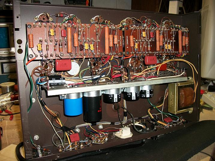
Here is a photo of the underside with Jim McShane parts.
Regards,
Sal
Attachments
"Actually, the Citation II is not at all requiring excellent OPT's like a williamson would; the FB is not all delivered in a front-to-back loop."
True, most of the feedback is in front of the OT. It also commits a serious error in placing two feedbacks to the same 12BY7 splitter grid inputs. Both control loops cannot be satisfied at the same time, so a compromise is the result. The inner 12BY7 splitter plate to grid feedbacks lowers the loop gain for the outer KT88 primary to splitter grid feedback local loops (which are the important ones, see my comments elsewhere and below on "magic" Schade feedbacks).
The inner 12BY7 splitter P to G loop was probably necessitated by the unregulated screen voltage on the 12BY7 (and at a voltage well above the 12BY7 plates). It could be that Hegeman tweeked the screen resistor and the inner versus outer local Fdbk loops to get the resulting splitter compression to balance the output stage expansion in some low to middle signal range. Not the way I would do it: Get rid of the inner 12BY7 plate to grid loops. Fix the 12BY7 screen voltages. CCS tail on the splitter to balance. Get rid of the UL outputs. Equal primary side winding resistances.
-----------------------
"Smokingamp, the Citation II runs its g2 above the plate voltage."
The 12BY7 does have a wide plate voltage range below the screen voltage (top of page 3 on attached datasheet) before the screen current picks up sharply. So limiting the damage. But clearly the screen current is not strictly proportional to the plate current in that range (curvature of the screen current upwards when the plate current curve is curving downwards). So violating the constant sum of screen currents thru the 22K common screen resistor. Resulting in compression effects in the splitter.
http://scottbecker.net/tube/sheets/093/1/12BY7A.pdf
------------------------
I seem to also recall a statement by Bob Carver somewhere that Stu Hegeman had said the biggest mistake he would re-do was the UL outputs. That they let you down when the output stage needs the most current.
------------------------
The outer local feedback loops do seem to be one of the few cases I have seen of "magic" Schade feedbacks (RCA sorta uses it in their 50 Watt handbook amp). This requires equal winding resistances in the OT primary sides to sense current during class AB crossover. The current sensed (in addition to the normal voltage sensed Schade) Fdbk smoothes out the crossover, by as much as 20 dB. (See Broskie's article on fixing crossover dist.) Not sure whether the OT is resistance balanced or not here (or if anyone was even aware of the effect at the time). The very idea of the differential current feedbacks was patented later several times for SS in the 80's. Citation II and RCA 50 Watter may have just stumbled upon it by chance. Likely the real reason for the Citation II "magic".
I doubt very much that it was by accident/chance. Hegeman used similar circuitry in his earlier amps. In fact I believe the last amp he did before moving to H-K was a Lafayette (I can't recall the model #) and it is VERY similar to the Citation II in many areas.
I must say - just because it wasn't designed the way you or Doug would have done it doesn't mean it isn't very good. For an amp to have all the "mistakes" and "errors" pointed out in this thread it's amazing it's listenable at all. It's even more amazing to realize how so many people consider it to be such a fine piece of gear.
If Hegeman's PI/NFB design was lacking in so many areas, it strikes me as odd that his pronouncement about U/L being a big mistake would seemingly go unquestioned in light of his "bungling" of the PI/NFB circuitry.
BTW, if you look at a Cit II voltage chart you'll see the voltage amp 12BY7As (V1 & V4) are run with the screen voltages exceeding the plate voltages by a significant margin, 50-ish volts. Is this yet another mistake??
Are you sure the "errors and "mistakes" aren't just different approaches than you would have taken? I'd be interested in your thoughts. I certainly defer to your (and Doug's) design talent - I'm not in your league I'm sure! But I confess - I simply can't grasp how a design you both seem to consider so full of issues could produce such good results in the mind's eye of so many listeners.
It appears to me that the Citation II is designed with an element of distortion cancellation between the splitter stage and the output stage, rather than solely around conventional negative feedback. The plate to grid feedbacks of V2,V3 reduce the stage gain there, which lowers the effectiveness of the outer local feedbacks (OT primary to splitter grids). So from the viewpoint of purely negative feedback design it seems sub-optimal. But if the distortion cancellation between the stages works well, then fine, its simply another way. But usually distortion cancellation only works over a limited signal voltage range.
The output stage in class AB has an expansionist characteristic (at least up till saturation sets in) due to the gm of the output tubes increasing as current increases. (constant gm would be ideal). So some compression in the splitter can be played against that to compensate. The compression effect coming from the 22K common screen grid resistor when screen current kicks up at large amplitudes (ie, splitter plate V plunging further below the screen V, causing the screen voltages to sag).
I would guess that the amplifier may even clip smoothly with this setup if the splitter plate V drops into the sharply curved part of the 12BY7 screen current characteristic as the outputs reach saturation (sharply compressive gain then). The lowered local loop gains may even help to prevent the usual NFdbk forcing of squared signal tops at clipping. So the limited range of the cancellation scheme might be used to prevent hard clipping. Would require some measurements to see what is actually going on. This scenario would cause rather noticeably increasing distortion figures as the signal gets close to the max.
So my earlier comments are from the conventional optimised (maximized) negative feedback viewpoint. In light of the present day fashion of low feedback, Stu H. may have been moderating the feedback usage some ahead of his time. (when high feedback was in vogue) Although certainly not what would be called a low feedback design nowadays.
A high screen voltage on the input stage (V1), would seem to cause higher 2nd harmonic distortion from screen current effects. Can't imagine why he would increase that, well yes I can. P-P normally (ideally) has no 2nd harmonic dist. Maybe he wanted a smoothly rolled off dist. spectrum. The global feedback would keep it under control.
On the "magic" Schade feedbacks (not just ordinary Schade feedbacks) which use winding resistance of the OT primary to sense current for crossover distortion correction (using a differential stage to subtract them, aka the diffl splitter here), I have never seen any reference to that scheme in any tube books or articles. Seems to be obscure even in the SS realm.
Hawksford (80's) may be the best write-up on that (but for SS totem pole output designs). The tail resistance of the splitter would want to be high to take advantage of that differential function (and is moderately so in the Cit II). A CCS tail being ideal. And the OT primary needs to have equal resistances on the two sides to make it work well. I don't see any equalizing resistor in series on one side of the OT primary in the schematic, so this would require a special design OT.
The RCA handbook design I mentioned has way too low of a tail resistance in its differential driver to do any good for this. Although it does have the correct type of local feedbacks to work for this. So I don't think they were aware of this scheme. One would expect a research powerhouse to have found it first and published. (Hawksford was (is) at Essex Univ. and he did publish).
Do you have any specs on the Citation II primary side resistances? This would be the key. I'm rather curious for historical reasons if this setup was by design or accident. (Well, I mean accident from the perspective of the "magic" crossover dist. cancelling scheme.)
Last edited:
But I confess - I simply can't grasp how a design you both seem to consider so full of issues could produce such good results in the mind's eye of so many listeners.
That is a rather simple one Jim...
Taste varies quite widely; SE v. PP come to mind, eh?On the overall design, I find adequate gain and good performance( output Z, distortion, presented sonics, etc...) with a single Schade/E-Linear LTP front end. The Cit.II is quite sensitive, and a very light load to the linestage( be it passive or otherwise ). Three stages behind the volume control is more than enough.
cheers,
Douglas
That is a rather simple one Jim...
On the overall design, I find adequate gain and good performance( output Z, distortion, presented sonics, etc...) with a single Schade/E-Linear LTP front end. The Cit.II is quite sensitive, and a very light load to the linestage( be it passive or otherwise ). Three stages behind the volume control is more than enough.
The Citation II has what I would call moderate sensitivity, requiring 1.5 volts to drive it to 60 watts (about 22 volts output), a gain of 14.7. It presents a light load because it has a high input impedance (1 Meg stock) and with a pentode input there is essentially no Miller capacitance to drive.
One design aspect not mentioned here so far was Stu's demand that the amp be unconditionally stable into any load. As well, you probably know the amp (excluding the OPTs) had flat frequency response to the MHz range, and a full power bandwidth (+ zero, -1 db) of 18 to 40KHz and a 1 watt power bandwidth (+ zero, -1 db) of 2 to 80KHz. That was a design objective as well. And the rated THD of .5% at 60 watts out from 20-20K is very conservative. Doug, if you were to measure your amp with the improved power supply (assuming healthy tubes and signal circuitry) you'd likely see THD of about .1% at 60 watts in the 20-20K range - along with peak power in the 150 watt range, not 130 watts as is spec'd.
I appreciate your comment regarding "taste" being the rationale for your observations in your posts. I did not read them that way initially.
To smoking-amp... I surely don't consider myself a designer in the same league as you or Doug - certainly not the same as Stu Hegeman!! But I can tell you that yes, there is significant distortion cancellation occurring between the splitter and output stage. Based upon our experiments with a CCS in the "tail" of the PI (instead of the 5K resistor) I can tell you that achieving an essentially "perfect" AC balance in the PI creates other issues that in turn require other changes in the output stage to achieve the desired performance. This finding is consistent with Stu's "gain-block" design - a change to any of the gain blocks will require changes in others so they can play happily together.
With all due respect to Doug and smoking-amp, it seems to me that a lot of aspersions are being cast at the amp based on speculation about how it works! It's clear to me the design was over the head of most designers back in the day - and probably still is! If it weren't, I'm sure it would have been copied many times by now - yet it remains the only amp that utilizes this unique topology.
That topology creates a real challenge for the long term too - as the supply of video pentodes such as the 12BY7A dwindles it is creating a need to be able to retube the Cit II with tubes in adequate supply (meaning - for all intents and purposes - currently being produced). We've done some preliminary work on this topic - and it is a daunting task indeed.
To close, here is a section of an email written to me a few years ago by my friend Dr. Norm Thagard (space shuttle astronaut, physician, educator, and long time audio design associate of Nelson Pass'). We were discussing using the 12GN7 as a sub for the 12BY7A. The 12GN7 has a Gm of about 36K uMhos, about 3X that of a 12BY7A:
Jim's note - R3 and R38 are the 220 Ohm cathode resistors on the A and B channel input 12BY7As, R33 and R68 are the 6.8K loop NFB resistors from the 16 Ohm tap to the input tubes' cathodes; continuing...I was in error about the tripling of the open-loop gain with the tripled transconductance. That would be true in the absence of cathode degeneration, but the use of R3/R38...
...makes the open loop gain less sensitive to tube transconductance. In fact, the gain is R/(rk + Rk), where R is the Thevenin-equivalent resistance to ground seen at the plate, rk = 1/gm is the intrinsic cathode resistance, and Rk is the extrinsic cathode resistance. In this case, Rk is the parallel combination of R3/R38 and the impedance seen looking from cathode to the R33/C12,R68/C28 feedback network.
The mid-frequency closed loop gain should be 1 + R33/R3 = 32. However, if this were true, the amp's sensitivity would be 60W output for 1Vrms input, which is the sensitivity I shoot for in my own amp designs. This comes from Vin-max = Vout-max/(1 + R33/R3) = [SQRT(60W x 16ohms)]/(1 + R33/R3) = 1V/32 = 1V. However, according to H-K, sensitivity is lower than this at 60W for 1.5Vrms. Actually, sensitivity should be higher than 60W for 1Vrms since the parallel resistance of R3 and 1/gm should be used in the calculation rather than just R3. I haven't been able to figure out why my calculation doesn't jibe with theirs. Perhaps you can tell me where the error is.
He's asking ME for help in determining the correct answer??
I think it's safe to say there is still much going on in that amp that is not widely acknowledged nor well grasped.
An interesting test would be to measure the Cit II FFT dist. spectrum at different power levels with and without an electrolytic cap across the R22, 22K Ohm, splitter common screen grid resistor. I would expect the stock (no electrolytic) setup would give reduced odd harmonic distortion at low levels (normal listening level, or the THD test spec power lever) versus the Elec. cap, and not much effect at say 1/4 to 1/2 max power, but to increase odd harmonics at say 3/4 to Full power (as strong splitter compression begins to round off the peaks).
On the possible "accidental" status of the "magic" Schade feedback scheme in the Cit II, I should add (might as well tee off Broskie too this morning ) that it is not clear from Broskie's rightup that he figured out the normal (CT'd OT) P-P configuration for it either. Despite obviously trying. (He presents an obtuse tube version with totem pole configuration, mimicking the SS patent example). I seem to be the only one pushing this idea in normal P-P tube configuration (CT'd OT). Although it becomes rather obvious once one sees the solution topology.
Broskie's writeup (bottom):
European Triode Festival and Crossover Notch Distortion and New OTL Design
I would also like to say that despite my earlier quibbles over the feedback versus (modest) cancellation mode of operation in the Cit II, that the first sighting of apparent "magic" Schade crossover distortion cancellation is a Salute to the Cit II, accident or not. The excellent reputation of the Citation II definitely adds to my quality asessment for Schade feedbacks to the input of a differential stage.
Last edited:
Cloning the Cit. 2 is no easy matter. The O/P trafos are among the BEST ever made. Bandwidth is phenomenal. .
Who actually made the o/p trannies for the Cit ?
richy
On re-tubing the Cit II, I would hazard the guess that the screen current curves will have to be similar to the 12BY7 if minimal changes are to be made. Otherwise, tweeking of R22, the screen source voltage itself, and the inner Schade Fdbks (R9,R17), and possibly some cathode degeneration resistors between the splitter cathodes. The inner Schade feedbacks, up at 1 Meg Ohm, look like they were tweeks, adjusting the stage compression response to fit the output stage.
I think it was Freed that made the later Cit II OTs.
I think it was Freed that made the later Cit II OTs.
- Status
- This old topic is closed. If you want to reopen this topic, contact a moderator using the "Report Post" button.
- Home
- Amplifiers
- Tubes / Valves
- Harman Kardon Citation II PI question