Glad to hear you are making progress. Well, you could remove the short on C6 and verify that you get around 1.2V across R33, give or take depending on the BIAS setting of P2.
If you get that, things are looking much better.
If it is possible or convenient at all see if you could test each Fet on its own, some should stand out and behave differently than others. Also double check the Gate resistors again. Perhaps you could remove the Fets, noting the location of each and test them under light load condition, the bad one should be easy to spot. I suspect that one or more Fets are half dead, crypled still working somewhat but when loaded they may do funny stuff...
I find C401 curiously located at Q401 but other FETs do not seem to have a Cap, I am not sure why that is, seems interesting to me what a possible reason it could be.
Before you install new Fets, be sure you set P2 such that the voltage across R33 is its lowest e.g. low BIAS current setting, so you do not accidentally start of with high BIAS current when turning on after the repair.
Also you could double check the voltage drop over D11 and D1, should be about 0.7V and over D12, D13 should be what the zehner spec. of these diodes says.
Last edited:
Glad to hear you are making progress. Well, you could remove the short on C6 and verify that you get around 1.2V across R33, give or take depending on the BIAS setting of P2.
If you get that, things are looking much better.
If it is possible or convenient at all see if you could test each Fet on its own, some should stand out and behave differently than others. Also double check the Gate resistors again. Perhaps you could remove the Fets, noting the location of each and test them under light load condition, the bad one should be easy to spot. I suspect that one or more Fets are half dead, crypled still working somewhat but when loaded they may do funny stuff...
I find C401 curiously located at Q401 but other FETs do not seem to have a Cap, I am not sure why that is, seems interesting to me what a possible reason it could be.
Before you install new Fets, be sure you set P2 such that the voltage across R33 is its lowest e.g. low BIAS current setting, so you do not accidentally start of with high BIAS current when turning on after the repair.
Also you could double check the voltage drop over D11 and D1, should be about 0.7V and over D12, D13 should be what the zehner spec. of these diodes says.
I'll see what I get when I remove the C6 jumper and I will also double-check the diode/zener values.
I have no problem removing the FETs to test. I did the simple FET test per the youtube video with them removed. Is there something else I can do to test them removed? Or by light load do you mean what I was saying about installing one pair and testing in the amp? My thought process was to install a single pair and see if the bias/circuit remains stable. If it does then those FETs are OK?
If I can narrow down the good FETs I may have enough to keep originals in place as my source only has a few pair. I have a feeling the other channel will have a few blown transistors so I may be buying a full set of Exicons in the near future.
I did notice the extra cap on the positive rail. The output stage isn't equal as the resistors for the + section 470ohm while the - section is 220 ohm.
Test the Fet like that, may be not as crudely with fingers as seen in the video but use a 10k resistor instead and perhaps a variable power supply e.g. 9V battery with potentiometer which allows to find the exact ON voltage for each transistor. This might help also to find which make a good pair.
https://youtu.be/y57O0uuSaE0
https://youtu.be/ORVukSfo9gc
See if they can drive a small / medium light bulb like that.
I would not attempt to test them in the amp. Do it outside the amp, it is more convenient to compare.
Can you post a picture and part number of these Fets ?
Don't worry about the cap, I find the single cap curious, that's all.
What are the parts numbers on the FETs? "QP113, 2" and "QN113, 4" for example? The last number is the sorting number done by Hafler. Unless you can sort the new ones I would recommend all new matched FETs or get some good used ones with the same sorting number. Hafler possibly sorted according to the gate threshold voltage.
Craig
Craig
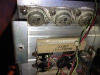
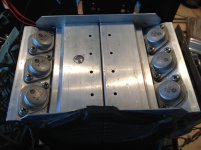
Here are some pictures of the mosfets. The schematic labels the parts as QN113 and QP113. On the actual FETs there are stamps that probably correspond with the batch code. Probably going to be pretty tough finding more with that specific stamp.
From what I read these FETs need to be closely matched to function appropriately. All my tests point to a faulty FET so I am thinking if one or two are bad I am probably not gaining anything by testing each one as putting a couple random used original FETs won't cut it.
Looks like a set of Exicon FETs will be in my future.
Attachments
Was thinking about this a little more. I am wondering if when I re-installed the mosfets I screwed up on keeping the N/P pairs together. Would this give me the changes I am seeing?
If not, I noticed both channels are from the same batch. Maybe I can get one working set from these and buy a matched set for the other channel. Waiting to hear back about the batch code from the potential source. Did see a person on eBay three pairs of output FETS that have the same batch code. Claims they are original but you know how that goes.
If not, I noticed both channels are from the same batch. Maybe I can get one working set from these and buy a matched set for the other channel. Waiting to hear back about the batch code from the potential source. Did see a person on eBay three pairs of output FETS that have the same batch code. Claims they are original but you know how that goes.
Removed the jumper across C6 and I am getting accurate voltages everywhere on the board!!
I guess at this point I will try and put the output stage back in and see what happens.
Currently without the output stage I get no current across the fuse but I am getting a change in both the +\- 1.2V so I am able to adjust close to that value.
Slow and steady.
I guess at this point I will try and put the output stage back in and see what happens.
Currently without the output stage I get no current across the fuse but I am getting a change in both the +\- 1.2V so I am able to adjust close to that value.
Slow and steady.
Removed the jumper across C6 and I am getting accurate voltages everywhere on the board!!
I guess at this point I will try and put the output stage back in and see what happens.
Currently without the output stage I get no current across the fuse but I am getting a change in both the +\- 1.2V so I am able to adjust close to that value.
Slow and steady.
Perfect. You are on the right track.
")
Not sure what you mean with screwed up on keeping the N/P pairs together. It is advisable not change the pairing as it was. But then it may not matter anymore if the Fets are half dead anyway.
Do the Fet verification one by one and see if you can find one or two that function different than the others. This could be the half dead one(s).
With the half dead one left out, install the remaining pair and see if the amp balances to zero and if you can adjust idle BIAS to spec. Of courcse you do not want to load the amp fully but it should perform decent to about 50% of its rated power.
I went ahead and tried with the fets back in and I was back at about -700mV on the negative side and +1.2V on the positive. Tried adjusting the bias and I couldn't get more than 100mA before the bulb got really bright. Had to drop it down to almost nothing to get the relay to kick in. Double checked the resistors and they are well within spec.
I'll pick up a battery this weekend and test the fets as described in the videos. My concern is that even if I do find a bad fet I'm not sure I can get another matching pair.
All the pictures I find of DH-500 and P-500 amps shows a number on them in marker. I believe this is the way they matched the fets. Would this be some sort of gain? Either way I do not have marking like this on my fets.
So I am still waiting to get the battery. In the mean time I couldn't resist messing with the amp. I removed all fets and tested each pair individually. The same result with all three pairs. Is that coincidence or could each fet be suffering the same failure? Kind of tough to think that could happen but I don't know enough to say one way or the next.
I have been in contact with someone who fixes haflers and they informed me of what voltages to expect for turn on values. The negative fets have a lower turn on voltage. I assume that's why the resistors are different on each side. Hopefully I can test them this weekend.
Gonna work on fixing the other channel and see how those fets fare on that side. Might try a pair on that side to test the rebuilt side. If those cause the same problem then I'll look at completely rebuilding the output stage (resistors and caps).
I would not recommend to put Fets from the current repair into another channel. They could take out your drivers and do more damage to the other channel. It is best to investigate them as is one by one with some loading. It is possible that all three have failed as they are in parallel circuit, if one dies milli seconds later the next dies and again a few milli seconds the last dies on one raiil. Then it is possible that the Fets on the other rail also get damaged in this fashion. They may all be compromised, crippled or half dead.
But that is speculation on my part and assumption of worst case until proven otherwise.
But that is speculation on my part and assumption of worst case until proven otherwise.
I agree^^^.
After sending most of my original parts to the altar of smoke and fire, I started to question whether or not I would follow such a path. After reading several cases of similar failures, I noticed that they nearly all ended the same way with the person having given up after destroying one or two sets of replacement parts.
Part of the problem I believe is the partial failure of a pert that is hard to discern at lower testing voltage/load.
With that, a pair of known driver boards and a full set of exicons has performed as expected.
Not as much of a challenge I'm sure, but...
I'm somewhat jealous since I denied myself of that life experience, I did look at it enough to almost get my head wrapped around it though. That is when I realized that my limited budget may run out before the amp was fixed...
There are also some simple mods/updates to improve these amps that are from later implementations by Erno Borbely, the designer of these amps. Have to get it functioning first though.
There are also some simple mods/updates to improve these amps that are from later implementations by Erno Borbely, the designer of these amps. Have to get it functioning first though.
So work put a major stall on repairing this amp.
I had some time recently, and per the advice of the guy (qua-co) on eBay, I have spent more time on the driver board. He was convinced the jets were fine and there was something wrong the the pre-driver. I wasn't convinced but since the price tag of new Fets was through the roof, I investigated more. Al the 47K resistors and a few more (can't remember) were replaced. I also replaced on the 1n4148 diodes as they are pennies.
Brought it up with a single Fet pair and the unit worked as appropriate and I was able to adjust the bias. I installed all Fets and the unit is working!! I am able to bias appropriately and the Fets warm up evenly.
Wish I could say which resistor/diode was the culprit but I something was off although DMM readings were OK. Still need to work on the other channel but I now have a template to compare.
I want to thank everyone here for their expertise and guidance. I also would like to thank qua-co as I was ready to buy new boards and new gets from him (I actually made the purchase) but he insisted that we spend a little more time problem solving. Not too many people these days willing to help out and lose money on their end.
Not totally done but this has been a great learning experience. Will keep updating as I work on the other channel.
- Status
- This old topic is closed. If you want to reopen this topic, contact a moderator using the "Report Post" button.
- Home
- Amplifiers
- Solid State
- Hafler P-500 Restoration