Here is a description of what I did with a pair of circuit cards,
P-19C, the version used on the DH-220, P-225, P-230, DH-500
and P-505 Hafler amplifiers. All these amps use this same circuit
card with only a slight change in two resistors for the
DH-500/P-505 models. So, I suppose, experiments with them
could have relevance to several different amplifier models.
For years I have never really been taken by the sound of the
DH-220 as it was too bland and lacking in highs and lows. The
P models were even worse, perhaps because of the extra wiring
for the bridging circuit and level controls. So, I was not expecting
much when I began to mess with non-stock mods on the use of
the P-19C circuit cards. My variations are not major, at least not
yet, so I will try to be brief in the description of what I have done
with them and the sonic payoffs of my modest mods.
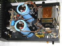
1. Dual mono or monoblocks. Took the right hand heat sink from
one amplifier chassis and mounted it on the left hand of a 2nd
chassis and with an extra transformer, switch, PS caps, etc.,
had a pair of monaural amplifiers. Their transformers were
moved to the right end to better balance the weight and to
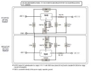
provide ample space for larger PS caps. Also installed an AC
powered time delay relay in each set for ~7 seconds to cancel a
50 ohm 20 watt AC surge resistor (see picture below).
2. Removed the wiring of the speaker fuse loop by jumpering
eyelets 6 and 8 together. Speaker output from eyelet 5 is now
daisy-chained through the back panel fuse and then to the red
speaker terminal. The black speaker terminal is attached to the
circuit ground between the two PS caps. Speaker ground output
from eyelet 7 now goes directly to main circuit ground.
RCA input is not floating but is the chassis ground reference
point. Its two wires go to eyelets 1 and 2 on the circuit card.
Also, the ground side is attached to the main circuit ground.
3. First auditioned them with the stock 10 K uF Sangamo PS
caps and found the monoblocks improved spaciousness and
breadth of sound stage but the overall sound was still the bland
old DH-220 sound from the past. Then, installed a 10 year old
set of 25K uF PS caps from Musical Concepts. Sound improved
with better inner detail and lower mid and upper bass warmth. I
could hear that progress was being made to get a really good
sound. Then, installed my trusty old set of 42K uF pairs of PS
caps in each mono amp and the sound really took off! The
blandness was gone and the sound became detailed with depth
and good left/right definition and stability of audio images. Plus,
a better sense of inner nuanced presence became more
apparent. Finally, the last addition is a pair of 1400 uF caps to
bypass each PS cap. These 1400 uF are nothing special, just
snap in electrolytic models from Illinois Capacitor. However they
provide a slight improvement in the lower mid and upper bass
area.
4. No changes made to C1 or C8. Some versions of this circuit
card had a 470 uF non-polarized cap for C8 instead of the
present 220 mfd. In a previous thread and message DJK talked
about "poles" and the relationship between input and feedback
cap values and overall PS cap values. This is a little beyond my
pay grade but it seems that the poles should be lined up and
coordinated appropriately. What would be the best set of caps
for these locations? If the PS capacitance has been boosted to
84 K uF per channel Would 470 mfd for C8 provide a better low
end? Ditto for a C1 of, say, 5 mfd instead of the present 2 mfd?
5. Summary. The good and the bad (no ugly). The monoblocks
effectively double the amount of transformer current capacity
available and, obviously, 84 K uF of capacitance in each PS is
far beyond stock. These monoblocks sound superior to a stock
amp and they improved greatly the perceived separation
between channels. I find that the volume is now turned up a tad
with no apparent sense of increased loudness but then I realize I
am hearing everything better. Lower distortion I guess makes
the sound seem not quite as loud. They also bring out more
detail, both good and bad, in some of my favorite CDs. The
Diana Krall "Live in Paris," for example, seems to have tape
splices and obvious cranking of the gain controls throughout
various tracks. The hiccups (tape splices) were so noticeable I
got the same CD from the local library to compare to my CD,
thinking it might be damaged. Both CDs sound exactly the same
so the imperfections now heard with monoblocks are really on
the CD, not in my system.
Now, what else to do? Can anyone suggest anything cost
effective to do?
Thanks for your attention to this.
P-19C, the version used on the DH-220, P-225, P-230, DH-500
and P-505 Hafler amplifiers. All these amps use this same circuit
card with only a slight change in two resistors for the
DH-500/P-505 models. So, I suppose, experiments with them
could have relevance to several different amplifier models.
For years I have never really been taken by the sound of the
DH-220 as it was too bland and lacking in highs and lows. The
P models were even worse, perhaps because of the extra wiring
for the bridging circuit and level controls. So, I was not expecting
much when I began to mess with non-stock mods on the use of
the P-19C circuit cards. My variations are not major, at least not
yet, so I will try to be brief in the description of what I have done
with them and the sonic payoffs of my modest mods.
1. Dual mono or monoblocks. Took the right hand heat sink from
one amplifier chassis and mounted it on the left hand of a 2nd
chassis and with an extra transformer, switch, PS caps, etc.,
had a pair of monaural amplifiers. Their transformers were
moved to the right end to better balance the weight and to
provide ample space for larger PS caps. Also installed an AC
powered time delay relay in each set for ~7 seconds to cancel a
50 ohm 20 watt AC surge resistor (see picture below).
2. Removed the wiring of the speaker fuse loop by jumpering
eyelets 6 and 8 together. Speaker output from eyelet 5 is now
daisy-chained through the back panel fuse and then to the red
speaker terminal. The black speaker terminal is attached to the
circuit ground between the two PS caps. Speaker ground output
from eyelet 7 now goes directly to main circuit ground.
RCA input is not floating but is the chassis ground reference
point. Its two wires go to eyelets 1 and 2 on the circuit card.
Also, the ground side is attached to the main circuit ground.
3. First auditioned them with the stock 10 K uF Sangamo PS
caps and found the monoblocks improved spaciousness and
breadth of sound stage but the overall sound was still the bland
old DH-220 sound from the past. Then, installed a 10 year old
set of 25K uF PS caps from Musical Concepts. Sound improved
with better inner detail and lower mid and upper bass warmth. I
could hear that progress was being made to get a really good
sound. Then, installed my trusty old set of 42K uF pairs of PS
caps in each mono amp and the sound really took off! The
blandness was gone and the sound became detailed with depth
and good left/right definition and stability of audio images. Plus,
a better sense of inner nuanced presence became more
apparent. Finally, the last addition is a pair of 1400 uF caps to
bypass each PS cap. These 1400 uF are nothing special, just
snap in electrolytic models from Illinois Capacitor. However they
provide a slight improvement in the lower mid and upper bass
area.
4. No changes made to C1 or C8. Some versions of this circuit
card had a 470 uF non-polarized cap for C8 instead of the
present 220 mfd. In a previous thread and message DJK talked
about "poles" and the relationship between input and feedback
cap values and overall PS cap values. This is a little beyond my
pay grade but it seems that the poles should be lined up and
coordinated appropriately. What would be the best set of caps
for these locations? If the PS capacitance has been boosted to
84 K uF per channel Would 470 mfd for C8 provide a better low
end? Ditto for a C1 of, say, 5 mfd instead of the present 2 mfd?
5. Summary. The good and the bad (no ugly). The monoblocks
effectively double the amount of transformer current capacity
available and, obviously, 84 K uF of capacitance in each PS is
far beyond stock. These monoblocks sound superior to a stock
amp and they improved greatly the perceived separation
between channels. I find that the volume is now turned up a tad
with no apparent sense of increased loudness but then I realize I
am hearing everything better. Lower distortion I guess makes
the sound seem not quite as loud. They also bring out more
detail, both good and bad, in some of my favorite CDs. The
Diana Krall "Live in Paris," for example, seems to have tape
splices and obvious cranking of the gain controls throughout
various tracks. The hiccups (tape splices) were so noticeable I
got the same CD from the local library to compare to my CD,
thinking it might be damaged. Both CDs sound exactly the same
so the imperfections now heard with monoblocks are really on
the CD, not in my system.
Now, what else to do? Can anyone suggest anything cost
effective to do?
Thanks for your attention to this.
Attachments
monoblock
Dick,
Interesting idea. I always thought that the DH-200/220 was limited on the power supply for a more than 100W amp. I wonder how the mono amp configuration using the 2 channels sound?
Increasing the power supply capacity that much I have no doubt that it sure has a big effect on the sound!
I know I have heard before to bypass the output fuse but I am not sure of the real bad effect it does (provided that the fuse has not aged) on the sound. With the fuse installed I get a damping factor of more than 500 at 1KHz. Also, removing the fuse expose the speaker tp possible excessive current in case of failure of the amp.
Your picture shows 3 pairs of mosfets instead of 2 pairs as in the original DH-220 I believe? The chassis switch position and high temperature alarm lamp also suggests a DH-200?
I know you have mentioned your appreciation of the Musical Concept board in previous posts. Have you got the chance to try it out on the monoblock too?
Regarding improvement, I guess that you have plenty of room to add a front end regulated power supply.
fab,
You are observant. The basic amp chassis is that of an early DH-200 version and the heat sink and 6 MOSFETs are from a P-230 or XL-280, but the circuit card is the basic one found on a variety of Hafler amps. Since most of the "sound" of an amp comes from its circuit card I thought it might be instructive to experiment with a monoblock and modified version of the basic power supply with minor wiring changes of the DH-220 to P-505 series of Haflers. The difference in sound between 4 and 6 MOSFETs per channel is slight, mostly in transient "slam" to drum percussives and bottom bass heft, but the basic character of the amp's sound remains the same.
The point I really wanted to make was the change in character of the DH-220 sound that occurred with PS upgrades. The DH-200 has its own sound and improvements to its power supply are worthwhile to do but they don't really change the basic sound of the amp. The DH-220 has always been bland to my ears but the changes I made seemed to help the "real" amp that was hidden inside to come out into the open and produce a much different and improved sound.
Bypassing the speaker fuse loop made a slight change in a DH-200 I modified earlier and this time I did not try a before and after. I just bypassed the speaker fuse loop. However, the speaker output of the circuit card now does go to the speaker protection fuse and then on to the speaker output jack, just as the XL-280 and DH-120/SE-120 are wired. This wiring still protects both the circuit and the speakers from major voltage faults.
Next will come a comparison between it and a similar set up with the MC PA-3B circuit cards, once I get a few more pennies saved up. But, it is interesting that no major set of mods have been done for the DH-220 -- P-505 series of amps that all use this circuit card. Is it that good or do people not care and prefer to go on to something different?
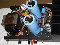
The is the other half of the monoblock pair:
Dick
You are observant. The basic amp chassis is that of an early DH-200 version and the heat sink and 6 MOSFETs are from a P-230 or XL-280, but the circuit card is the basic one found on a variety of Hafler amps. Since most of the "sound" of an amp comes from its circuit card I thought it might be instructive to experiment with a monoblock and modified version of the basic power supply with minor wiring changes of the DH-220 to P-505 series of Haflers. The difference in sound between 4 and 6 MOSFETs per channel is slight, mostly in transient "slam" to drum percussives and bottom bass heft, but the basic character of the amp's sound remains the same.
The point I really wanted to make was the change in character of the DH-220 sound that occurred with PS upgrades. The DH-200 has its own sound and improvements to its power supply are worthwhile to do but they don't really change the basic sound of the amp. The DH-220 has always been bland to my ears but the changes I made seemed to help the "real" amp that was hidden inside to come out into the open and produce a much different and improved sound.
Bypassing the speaker fuse loop made a slight change in a DH-200 I modified earlier and this time I did not try a before and after. I just bypassed the speaker fuse loop. However, the speaker output of the circuit card now does go to the speaker protection fuse and then on to the speaker output jack, just as the XL-280 and DH-120/SE-120 are wired. This wiring still protects both the circuit and the speakers from major voltage faults.
Next will come a comparison between it and a similar set up with the MC PA-3B circuit cards, once I get a few more pennies saved up. But, it is interesting that no major set of mods have been done for the DH-220 -- P-505 series of amps that all use this circuit card. Is it that good or do people not care and prefer to go on to something different?
The is the other half of the monoblock pair:
Dick
Attachments
Repair of DH-220 circuit board
I now have an extra DH-220. This one has a dead channel. There is no drive to the output MOSFETs on that channel, no voltage to their gates, nothing. And no evidence of anything burned, etc.
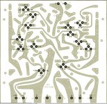
At the bottom I have posted a picture of the DH-500 test points and voltages. The DH-220 uses the same circuit board with all parts the same, so one should be able to interpolate the voltages shown down from 90 VDC to 65 VDC.
What I find is that all the voltages are very close except when I get to Q8 and Q11, neither of which has any output from their collectors. They are supposed to present +/- 1.5vdc to the base of the drivers Q12/13. And, they connect to Q9 which helps set the bias current
Is the repair just that simple, just put in working transistors for Q8/11?
What might have blown them but have left everything else working? Q8/11 are supposed to be protected from overvoltages by D9 and D10.
Any comments or help? Before I install Q8/11 replacements is there anything else I should check out? Without knowing why these two transistors seemed to have failed I won't know if something in the circuit is still there which might blow replacements. What do you think?
Thanks ....... Dick
I now have an extra DH-220. This one has a dead channel. There is no drive to the output MOSFETs on that channel, no voltage to their gates, nothing. And no evidence of anything burned, etc.
At the bottom I have posted a picture of the DH-500 test points and voltages. The DH-220 uses the same circuit board with all parts the same, so one should be able to interpolate the voltages shown down from 90 VDC to 65 VDC.
What I find is that all the voltages are very close except when I get to Q8 and Q11, neither of which has any output from their collectors. They are supposed to present +/- 1.5vdc to the base of the drivers Q12/13. And, they connect to Q9 which helps set the bias current
Is the repair just that simple, just put in working transistors for Q8/11?
What might have blown them but have left everything else working? Q8/11 are supposed to be protected from overvoltages by D9 and D10.
Any comments or help? Before I install Q8/11 replacements is there anything else I should check out? Without knowing why these two transistors seemed to have failed I won't know if something in the circuit is still there which might blow replacements. What do you think?
Thanks ....... Dick
Attachments
after almost decade (or is it more?) in repair bussines ( if that is bussines ; ) I have one experience with power amps- easiest way for repair is so simple : desolder every transistor (off course-one by one ) and measure it in your favorite way,no matter what is your favorite way;
pretty offten you can't find any logical pattern why some part is burned; all you can is just to presume but ,I repeat , if your intention is primary repair- desolder and test one by one;
include and diodes too")
pretty offten you can't find any logical pattern why some part is burned; all you can is just to presume but ,I repeat , if your intention is primary repair- desolder and test one by one;
include and diodes too
Re: Repair of DH-220 circuit board
Hi Dick
When you say "no output" do you mean "floating" or steady 0 volt DC? if 0 VDC might be a short of either D11 through D14 or Q12 and/or Q13. Have you checked them?
voltages on the schematics would be easier to check than on the pcb...
Dick West said:I...What I find is that all the voltages are very close except when I get to Q8 and Q11, neither of which has any output from their collectors. They are supposed to present +/- 1.5vdc to the base of the drivers Q12/13. And, they connect to Q9 which helps set the bias current
Is the repair just that simple, just put in working transistors for Q8/11?...Thanks ....... Dick
Hi Dick
When you say "no output" do you mean "floating" or steady 0 volt DC? if 0 VDC might be a short of either D11 through D14 or Q12 and/or Q13. Have you checked them?
voltages on the schematics would be easier to check than on the pcb...
Referenced to circuit ground there is no voltage (0) to the gates of the MOSFETs. There is supposed to be around -0.8 to +1.0 volts at that point.
What is the probability that both D9 and D10 would fail shorted? If they failed "open" their condition would not effect circuit voltages, they just would no longer provide protection to Q8 and Q11. Ditto for D11, 12, 13, 14. They would have to fail shorted and on both sides of the circuit to take away the voltages at the collectors of Q8 and Q11 to ground. If they failed open then voltages would not be changed, there would just be reduced protection to Q12 and Q13.
So . . . all voltages are in spec up to the collectors of Q8 and Q11 and the bases of Q12 and Q13 -- from Q1 through Q10. But, no voltage is present at the collectors of Q8 and Q11. Therefore, it seems that Q8 and Q11 have failed open and produce no output voltage to drive the bases of Q12 and Q13.
I hope I am being clear.
just trying to help here...
if you really have 0 Vdc at Q8 Q11 collectors then it means you have a short to gnd and not open circuit (you would have floating voltage). What is strange is to have a 0 V at both Q8 and Q11. It is ONLY A POSSIBILITY but maybe both Q12 and Q13 have their b-e junctions shorted?
if you really have 0 Vdc at Q8 Q11 collectors then it means you have a short to gnd and not open circuit (you would have floating voltage). What is strange is to have a 0 V at both Q8 and Q11. It is ONLY A POSSIBILITY but maybe both Q12 and Q13 have their b-e junctions shorted?
I don't understand "floating" voltage. I attach the black lead to circuit ground and check voltages at various points with the red probe of my multimeter set to read VDC. How do I measure "floating" voltage?
Now, a normal circuit is supposed to present -1.35 and 1.54 vdc to the bases of Q12 and Q13. There is no voltage on the emitters of Q12 and Q13. If there were shorts between the base and emitters of Q12 and Q13, would the voltage presented to their bases come through to their emmiters, maybe with one diode drop?
I know you are trying to be helpful. I am just trying to present my logic as I see it from the voltages present. These voltages are checked against the table of voltages in the DH-220 manual and from those shown on the DH-500 picture of the back side of the circuit card. I have, of course, noted the differences because of the rail voltages between the DH-220 and DH-500.
I know it is silly to throw parts at a circuit until a thorough job of sleuthng and trouble shooting has been done. Whatever happened was done to both the + and - sides of the circuit as there is no drive voltage to the gates of the MOSFETs, both the N and P channel devices.
"floating": I mean with no reference like when 1 of the 2 probes of the multimeters is not connected to anything the voltage display changes randomly.
When there is a short there is no more "diode" voltage drop anymore in the transistor since it is "broken". I would check Q12 and Q13 Vbe with no power applied with meter in diode mode. But you can be fooled if the D11 to D14 are failed.
In fact, I would also check Q8 and Q11 the same way.
When there is a short there is no more "diode" voltage drop anymore in the transistor since it is "broken". I would check Q12 and Q13 Vbe with no power applied with meter in diode mode. But you can be fooled if the D11 to D14 are failed.
In fact, I would also check Q8 and Q11 the same way.
Why would I attempt to measure circuit voltages with one of the probes not connected? Is this what you mean by "floating?"
Well, I guess I will have to begin to unsolder some parts. I was hoping to only do soldering to replace a faulty part. But to check the condition of the diodes one end must be lifted, and to check the be junctions of the transistors they will have to be removed from the circuit. Drat! My soldering tools and skills are not real good. I'm still having some hand tremors since some serious surgery a few months ago. But, I'll be careful and hope for the best.
I would guess that the drivers are suspect. The pre drivers are protected by D9 and D10. The drivers usually are first in line to take the brunt of abuse. I think the previous owner was driving ESL speakers with the amp and also was using slow blow fuses in the speaker protection fuse blocks! Go figure!
Thanks for your help. I'll post tomorrow with results of diode and driver transistor checks -- out of circuit.
I disconnected D11 and D14 and checked all diodes, D11 through D14. They are all OK. Ditto for D9 and D10. With the diodes still disconnected I brought the voltage up on the circuit card. There is still no output (collector voltages) from the pre-drivers Q8 and Q11. Therefore, if they send no voltage to the bases of the drivers Q12 and Q13 there would be no voltage at the gates of the MOSFETs.
The pre-driver and driver transistors all have a small finned heatsink attached to them. All 4 of these transistors run stone cold. They are doing no "work," they create no heat. Now, if the base/emmitter junction of the drivers were shorted they would still create a load on Q8 and Q11 (the pre-drivers) and cause these two transistors to at least get warm. Right? Plus, if the base/emmitter junctions of the drivers have failed "open" any voltage from the pre-drivers would still be pesent at the bases of the drivers -- so it would seem.
Therefore, logic makes it very likely that the pre-drivers, Q8 and Q11, are the culprits and need to be replaced. Also, the drivers show no indication (with meter probes) that their be junctions are shorted. The drivers may also need to be replaced but I won't know that until the pre-drivers send them some base voltage to work with.
How is that for logic? Any ideas one way or the other?
Dick
Dick West said:Why would I attempt to measure circuit voltages with one of the probes not connected? Is this what you mean by "floating?"
It was just to explain "floating" voltage effect not to actually perform it.
Hexfred Bridge
I am ready to modify/tweak yet another DH200. I have read and re-read The power supply design document at:
http://www,zero-distortion.com
I want to try the dual power rectify bridges for plus and minus supplies. I would like to compare the hexfred and conventional bridges. I have three DH200 to work with. So I will have a chance to A/B them.
Recommendations for Hexfred and conventional bridges would be appreciated. For dual rectification will I need bridges rated as high as the originals?
I saw in a post earlier on where IXYS hexbridges had been implemented. Part numbers from Digi-key, Mouser, etc. would be a great help. TIA
DH220 mods
I hope there is still some interest in this thread.
I have incorporated several of the POOGE modes for the DH200 into my DH220. I have installed gold plated input sockets and replaced the input wiring with OFC cable. I have relocated the speaker fuses onto the pcb, with bypass capacitors. I have installed a copper bus bar between the psu caps, and rewired all the grounds through a centre tap on the bus bar.
I have also used rubber washers to isolate the transformer from the case. This has reduced a mechanical hum previously audible across a quiet room, now barely audible at 2 feet.
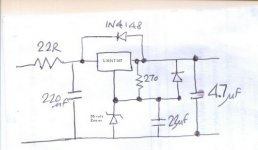
My next move will be to relocate the power supply fuses before the filter caps, as in the POOGE article. Then I intend to install regulators for the front end. The cct I'm going to use is shown below.
I would appreciate any comments on this plan, from experienced modders, before I move on to front end mods.
Thanks.
I hope there is still some interest in this thread.
I have incorporated several of the POOGE modes for the DH200 into my DH220. I have installed gold plated input sockets and replaced the input wiring with OFC cable. I have relocated the speaker fuses onto the pcb, with bypass capacitors. I have installed a copper bus bar between the psu caps, and rewired all the grounds through a centre tap on the bus bar.
I have also used rubber washers to isolate the transformer from the case. This has reduced a mechanical hum previously audible across a quiet room, now barely audible at 2 feet.
My next move will be to relocate the power supply fuses before the filter caps, as in the POOGE article. Then I intend to install regulators for the front end. The cct I'm going to use is shown below.
I would appreciate any comments on this plan, from experienced modders, before I move on to front end mods.
Thanks.
Attachments
I'm not sure I really qualify as an "experienced modder" but I have done my share of them on the DH-200 and DH-220.
Here is what I did to a pair of DH-220 circuit cards:
http://www.diyaudio.com/forums/showthread.php?postid=631761#post631761
One thing I guess you have not yet done is to improve the PS filter caps. A pair of 26K uF caps such as MusicalConcepts can provide should make a difference.
A thought on your proposed front end regulator. You really need to drive it with a voltage 10-15 ±vdc higher than what the output section sees. You need a higher voltage to regulate down to get a stable drive for the circuit cards. Also, the circuit cards should really run at a few volts higher than the output section to get maximum efficiency.
I have a Hafler XL-280 transformer that has two sets of secondaries that will provide you with the regular 65 ±vdc plus 75 ±vdc to run the regulator. Let me know if you are interested in it for $25 plus shipping. Something to consider. Or, you could purchase this one:
http://cgi.ebay.com/NOS-Hafler-POWE...828582839QQcategoryZ67815QQrdZ1QQcmdZViewItem
tchewtch said:I hope there is still some interest in this thread.
... Then I intend to install regulators for the front end. The cct I'm going to use is shown below.
I would appreciate any comments on this plan, from experienced modders, before I move on to front end mods.
Thanks.
hi tchewtc
Yes the driver regulator supply is a good idea for sound improvement.
I believe that the LM317/337 are adjustable regulators. The way you use them is not adjustable thus why not use 7818/7918 or 7824/7924 simple fixed regulators (probably cheaper). The 22 ohms input resistor is not really needed with these regulators.
Your input voltage of regulator needs to be at least 3 V higher than the regulator output to use the benefit of regulated voltage. What is your output voltage?
As Dick West indicated, for max efficiency the driver voltage should be higher than the mosfet voltage section. However, it is not the case in the original Hafler DH-200/220 amps. So if efficiency and max power output is not your primary goal but more the quality of reproduction, the regulated voltage at about 6 volts less than mosfet voltage section is beneficial. If you use an additional transformer or one with dual voltage (as the XL-280) with regulated driver voltage then you get max efficiency and sound improvement.
See attached circuit installed for several years in my DH-200 amps.
In another version I replaced the Zener with TL431.
Good luck
Fab
Attachments
Fab,
Nice circuit. Is there enough adjustment in it to allow it to work with the 75VDC of an XL-280 transformer? What component values would have to be changed?
I have read that it is preferable that the output stage clips before the driver circuit. Supposedly some really nasty sounds result if the low level circuit clips first. Therefore, the circuit card should run at a higher voltage that the output section. So some experts tell me. . .
I belive you have that backwords . By regulating the PCB down to 58 - 60 volts you also quasi regulate the outputs because they can't be driven to clipping .
I worked for musical concepts from 84 -87 and did PCB layouts for the MC1 ,MC2 and lipps ps . John also picked my brain when he left Marcoff electronics to start Musical Concepts for mods to the 200 . It was all Johns hard work ,good ears and componet selection that make Musical Concepts products great .
The highest failure rate on the pcb was the dual differtental input transistors which would lose DC beta and cause dc offset at the outputs and high freq oscilation . The bias transistor would short alot and replacing it with a better transistor is recomened .
I would sugest jumpering out the speaker fuse eyelets on the board and if you want fuses put them at the speakers away from the electrical noise . If your signal scorce has an output cap , the input cap can go .
Hope this helps someone .
Mark
- Home
- Amplifiers
- Solid State
- Hafler DH-200/220 Mods