Any info here? I'm one of the unfortunates who has the Z-5500 spring-loaded with NO PIN-6! So this is the setup related to a couple of posters, one of whom should get Karmic revenge for proclaiming that he got it working and then vanished with no details. People like that need some lightning strikes. 🙂 The sub definitely works - put it on the new system and had full audio.
Thanks
Thanks
hi, love the pics, i have a blown r22 next to the regulator. the wire in the photo is obstructing what it is.
Could anyone have a peek for me on theirs.
kindest regards
Steve
Orange, Blue, Black, Gold - measure 35 ohms on my fluke! 🙂
Any info here? I'm one of the unfortunates who has the Z-5500 spring-loaded with NO PIN-6! So this is the setup related to a couple of posters, one of whom should get Karmic revenge for proclaiming that he got it working and then vanished with no details. People like that need some lightning strikes. 🙂 The sub definitely works - put it on the new system and had full audio.
Thanks
Perhaps post 251 or the RCA version pinout could help
HELP!!!
Hello,
I need help to, I have the Z5500 and the warranty ended one year ago.
I had a problem. Some time ago I had to box the speakers again for a year and in meanwhile a didn't use them. After that when I connected again I suddenly noticed that the left speaker didn't work...for the first view I thought that was the speaker itself that was damaged and I tried to change with the right speaker to see if it work and it worked perfectly, I change the cables to and so on...so the problem was not in the speaker and probably was on the sub amp.
I called a friend (that knows about electronic stuff) to try to fix this problem, we thought that was one of the TDA that was burned and we replaced with one new TDA 7294, after that we turned on the equipment and nothing happened, I didn't see the red/blue light coming from the pod. We realize that the fuse and the "bridge rectifier" (I don't know if this is the right term, sorry) had burned. After a change of fuse and "bridge" the problems didn't stop and we started to see smoke going out from a 100ohms resistor near the transistors (where all the speakers cables go) when he was doing some measurements with the multimeter and we changed it.
After all this bad luck we try to do some test (using the option "test" from the pod) to see it it was all ok and for our surprise none of the speakers or sub worked, only the center speaker respond to the test doing the annoying sound...
My friend tried to see what was going on but he didn't have much time because he had to go away and after a quick analyze he spoke that all the TDA except the central one and one for the sub (I think that two of the TDA are for the sub) were in mute state, in other words, according to him all the TDA 7294 do not have current (+5v) on pin 10 or 9, i think so, that is the pin for "mute", that's why they don't play any sound.
I don't know much about electronic but I'm going crazy with this, no one can tell what is the problem and I can't find the solution to this, do you think that are solution to this or I have to buy a new set of speaker??
PLEASE HELP!!
If there is anything that is escaping me please let me know...
no power to pin 14
stunning post and ive savoured everything i can find , my problem is slightly different different tho , with pod all powers on then "turns off" display is still illuminated , working thro this post pin outs , my pin 14, +18v stops after about 6secs , voltage transistor is working well (getting hot) , and power to all amp circuits (35v), would bring biccies an hot coffee to any that can help ? problem is 100% amp/power side , z5500 spring clip version all pinouts work correctly except loss of voltage on pin 14 , start voltage on this pin is 17.2v no drop , just stops after 6 secs
hugs and kisses for help ,
No center output
Hi,
I use the Z5500 (RCA version) without control pod.
The problem is the center output does not work. All the others outputs work well.
I have done the connection given by UNDERTONE on page 2.
Does anyone have an idea?
Thanks for your help.
Regards.
Bastien
Hi,
I use the Z5500 (RCA version) without control pod.
The problem is the center output does not work. All the others outputs work well.
I have done the connection given by UNDERTONE on page 2.
Does anyone have an idea?
Thanks for your help.
Regards.
Bastien
Hi,
I use the Z5500 (RCA version) without control pod.
The problem is the center output does not work. All the others outputs work well.
I have done the connection given by UNDERTONE on page 2.
Does anyone have an idea?
Thanks for your help.
Regards.
Bastien
Hello,
Where do you get the +5v for pins 7 & 8 from ?
Regards!
hi
can anybody tell me the value of these couple of resistors in the image
ImageShack® - Online Photo and Video Hosting
thankss
can anybody tell me the value of these couple of resistors in the image
ImageShack® - Online Photo and Video Hosting
thankss
nice
i just wanna thank all the people who worked hard on the tracing for the z5500.
today i hotwired my z5500 for 15min time.
6-7-8 on 13 to power up the sistem,input as given by you guiz.
everithing works perfect!
i didn't have to do a downdrop on the woofer input because i wired everithing up with a mixer.
anyway my sistem is the springed-wire tipe.
first i tried with the negative technique and it turned on right away.
i also tried with the 5volt later so i can post if it works or not,on my sistem it does nothing,sistem stays down.
anyway thanks again guiz,you saved me a couple of hours of tracing 🙂
Hello!
Just as the poster above me, wanted to thank everyone in this thread for sharing all this information, thanks to you my Z5500 are now back from the dead and work perfectly.
Here's the info about my system:
PID: R512
Type: Spring-clip
First thing I did was bying a bypass cable off Ebay (because I'm lazy like that). The seller confirmed the cable follows this schematics (grounding version).
Unfortunately, just as I feared, the cable didn't work on my pre-636 system, the amps were still off.
So I decided to give the +5V version a try.
My wiring seems to be the same as the one xavijs has.
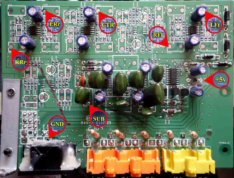
This (white) wire indeed turned the amps on. I fed +5V to it from the place undertone marked in this post of his.
With the amps turned on but without the cable (still the same one from Ebay) attached to the sub the speakers produced this "buuuu" sound xavijs was talking about. But with the cable connected everything was normal.
So I thought that was it and my speakers were all working, but when I started testing them I noticed that my center speaker didn't work. Same problem as Bastien had.
I had to experiment a little and found out that feeding +5V to the orange cable turns my center speaker on. 🙂 There's one condition though: orange and white wires must not be connected with each other otherwise the amps turn off. So I had to connect to the other side of that control logic's +5V which was pretty hard to do due to its miniature size. If you can't connect there without accidentally burning the smaller components I believe you can alternatively feed +8V to the orange wire that also turns the center on.
So in the end I use the cable with the grounding schematics, while separately feeding +5V to white and orange cables.
Everything works as it should.
Hope this helps.
Regards,
Toff
Just as the poster above me, wanted to thank everyone in this thread for sharing all this information, thanks to you my Z5500 are now back from the dead and work perfectly.
Here's the info about my system:
PID: R512
Type: Spring-clip
First thing I did was bying a bypass cable off Ebay (because I'm lazy like that). The seller confirmed the cable follows this schematics (grounding version).
Unfortunately, just as I feared, the cable didn't work on my pre-636 system, the amps were still off.
So I decided to give the +5V version a try.
My wiring seems to be the same as the one xavijs has.
This (white) wire indeed turned the amps on. I fed +5V to it from the place undertone marked in this post of his.
With the amps turned on but without the cable (still the same one from Ebay) attached to the sub the speakers produced this "buuuu" sound xavijs was talking about. But with the cable connected everything was normal.
So I thought that was it and my speakers were all working, but when I started testing them I noticed that my center speaker didn't work. Same problem as Bastien had.
I had to experiment a little and found out that feeding +5V to the orange cable turns my center speaker on. 🙂 There's one condition though: orange and white wires must not be connected with each other otherwise the amps turn off. So I had to connect to the other side of that control logic's +5V which was pretty hard to do due to its miniature size. If you can't connect there without accidentally burning the smaller components I believe you can alternatively feed +8V to the orange wire that also turns the center on.
So in the end I use the cable with the grounding schematics, while separately feeding +5V to white and orange cables.
Everything works as it should.
Hope this helps.
Regards,
Toff
Hello!
Just as the poster above me, wanted to thank everyone in this thread for sharing all this information, thanks to you my Z5500 are now back from the dead and work perfectly.
Here's the info about my system:
PID: R512
Type: Spring-clip
First thing I did was bying a bypass cable off Ebay (because I'm lazy like that). The seller confirmed the cable follows this schematics (grounding version).
Unfortunately, just as I feared, the cable didn't work on my pre-636 system, the amps were still off.
So I decided to give the +5V version a try.
My wiring seems to be the same as the one xavijs has.
This (white) wire indeed turned the amps on. I fed +5V to it from the place undertone marked in this post of his.
With the amps turned on but without the cable (still the same one from Ebay) attached to the sub the speakers produced this "buuuu" sound xavijs was talking about. But with the cable connected everything was normal.
So I thought that was it and my speakers were all working, but when I started testing them I noticed that my center speaker didn't work. Same problem as Bastien had.
I had to experiment a little and found out that feeding +5V to the orange cable turns my center speaker on. 🙂 There's one condition though: orange and white wires must not be connected with each other otherwise the amps turn off. So I had to connect to the other side of that control logic's +5V which was pretty hard to do due to its miniature size. If you can't connect there without accidentally burning the smaller components I believe you can alternatively feed +8V to the orange wire that also turns the center on.
So in the end I use the cable with the grounding schematics, while separately feeding +5V to white and orange cables.
Everything works as it should.
Hope this helps.
Regards,
Toff
Hello Toff,
Thanks for your help!
So, you're getting the +5v for the amp from the place marked in this photo?
I think it's too small for me to solder anything in that place.. Is there any other alternative? Maybe getting the +5v externally...
soflip
Yes, I managed to solder two wires there from both sides. It's important because when I tried feeding +5V from the same place (thus connecting orange wire with white) the amps turned off.
Alternatively you can get +8V from pin 10. +8V also turns the amps on, as someone said they expect anything above 3.5V, but I'm not sure how safe giving them higher voltage would be in the long-term perspective.
Of course, my PCB revision looks quite different from undertone's, mine is similar to the one xavijs has. I marked everything in this picture (did it by memory, hope I didn't mess up):
An externally hosted image should be here but it was not working when we last tested it.
d-sub 15 pin to stereo jack
Hi everyone,
i am trying to get my z5500 to work with a d-sub 15 pin to stereo jack.
My z5500 controller panel died. I tested the z5500 with another control panel.
With the other control panel (of a friend) it works fine.
I found this Thread and with the pic of knexkid i tryed to find
a way to get it working with a stereo jack.
I have no receiver and as i read here somewhere i dont need one...
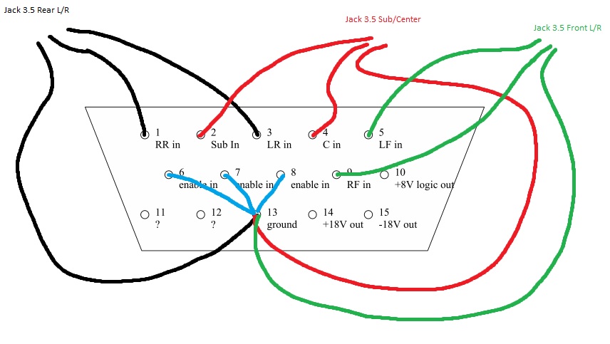
I took a d-sub 15 pin, 3 row connector and try this:
PIN 6, 7 and 8 are connected to 13 and there is a wire to ground of the stereo jack.
PIN 2, 3 and 5 are my Left Channel and
PIN 1, 4 and 9 are my Right Channel.
Ok i connected it with a Laptop and a media Player and it does nothing at all. 😕
Would be cool if anyone could give hints.
Sorry for my bad english.
Greetings
Oli
Hi everyone,
i am trying to get my z5500 to work with a d-sub 15 pin to stereo jack.
My z5500 controller panel died. I tested the z5500 with another control panel.
With the other control panel (of a friend) it works fine.
I found this Thread and with the pic of knexkid i tryed to find
a way to get it working with a stereo jack.
I have no receiver and as i read here somewhere i dont need one...
I took a d-sub 15 pin, 3 row connector and try this:
An externally hosted image should be here but it was not working when we last tested it.
PIN 6, 7 and 8 are connected to 13 and there is a wire to ground of the stereo jack.
PIN 2, 3 and 5 are my Left Channel and
PIN 1, 4 and 9 are my Right Channel.
Ok i connected it with a Laptop and a media Player and it does nothing at all. 😕
Would be cool if anyone could give hints.
Sorry for my bad english.
Greetings
Oli
I want to try to connect my z5500 to my onkyo nr509. I currently have a rca to mono jack and have put the rca in the sub pre out and the mono jack in my pod. This doesn't do anything. Maybe i am doing something wrong?
Anyway i like to to try soldering a cable with a rca on one side and a db15 on the other side. When readng this topic i notice a lot of different models.
The one i have is a spring-clip with pid r625. Does anyone know if i just can follow the general tips for the spring clip? If so, i should connect pin 6, 7, 8 and 13 to the ground of the rca and the male pin to pin 3 on the db15, right? 🙂
I want to try to connect my z5500 to my onkyo nr509. I currently have a rca to mono jack and have put the rca in the sub pre out and the mono jack in my pod. This doesn't do anything. Maybe i am doing something wrong?
Anyway i like to to try soldering a cable with a rca on one side and a db15 on the other side. When readng this topic i notice a lot of different models.
The one i have is a spring-clip with pid r625. Does anyone know if i just can follow the general tips for the spring clip? If so, i should connect pin 6, 7, 8 and 13 to the ground of the rca and the male pin to pin 3 on the db15, right? 🙂
I have just tried it and it works just fine! (ofc i used pin 2 and not 3🙂 )
I have no receiver and as i read here somewhere i dont need one...
I took a d-sub 15 pin, 3 row connector and try this:
An externally hosted image should be here but it was not working when we last tested it.
PIN 6, 7 and 8 are connected to 13 and there is a wire to ground of the stereo jack.
PIN 2, 3 and 5 are my Left Channel and
PIN 1, 4 and 9 are my Right Channel.
Ok i connected it with a Laptop and a media Player and it does nothing at all. 😕
Would be cool if anyone could give hints.
Sorry for my bad english.
Greetings
Oli
What's your system's PID? Is it spring-clip or RCA? What does your PCB look like?
Do you hear the amps turning on after you connect the cable to it? If you don't, you might need to feed +5V instead to some of those pins you grounded.
Just a side note...why not tap the voltage directly off of the voltage regulators that feed the opamps? If a lower voltage is needed a 5v reg can be added from the +15 adding only 2 wires and a capacitor. This seems like a safer approach rather than tapping a random source on the board. Under normal operation what is the feed voltage that switches the amps on and where does it come from?
Just a side note...why not tap the voltage directly off of the voltage regulators that feed the opamps? If a lower voltage is needed a 5v reg can be added from the +15 adding only 2 wires and a capacitor. This seems like a safer approach rather than tapping a random source on the board. Under normal operation what is the feed voltage that switches the amps on and where does it come from?
@Toffmonster
Thanks very much for your answer. I am starting to get hopeless.
I have this edition of the z-5500:
So I guess this is a "spring-clip" edition.
Is 4,5V or 6v and 300mA ok? Or more/less?
@crazifunguy
Thanks for your answer...
I think I first solve the first problem. The rest will be fine-tuning 😉
Incidentally, I make the crafts for a charitable project...so i hope
i have enough luck to get it working 😉
===EDIT===
Ok i tryed it and its not working... So it seems to be more than giving 5V between
Pin 6 and Pin 13... I dont hear anything. I dont see what i am doing wrong.
Perhaps anyone could give me some clues.
Thanks very much for your answer. I am starting to get hopeless.
I have this edition of the z-5500:
An externally hosted image should be here but it was not working when we last tested it.
So I guess this is a "spring-clip" edition.
No i get nothing at all. But with a control panel it works...Do you hear the amps turning on after you connect the cable to it?
Ok sounds good...do you know which pins? pin 6,7,8? or all of them?If you don't, you might need to feed +5V instead to some of those pins you grounded.
Is 4,5V or 6v and 300mA ok? Or more/less?
@crazifunguy
Thanks for your answer...
I think I first solve the first problem. The rest will be fine-tuning 😉
I dont know...but i will try first an external source with a 4,5V and 6V (300mA) Output between Pin 13 (i guess) and Pin 6 an/or Pin7.Under normal operation what is the feed voltage that switches the amps on and where does it come from?
Incidentally, I make the crafts for a charitable project...so i hope
i have enough luck to get it working 😉
===EDIT===
Ok i tryed it and its not working... So it seems to be more than giving 5V between
Pin 6 and Pin 13... I dont hear anything. I dont see what i am doing wrong.
Perhaps anyone could give me some clues.
Last edited:
Yes, that's spring-clip. Please, also check the PID number of your system, should be on a sticker at the bottom of your sub. It's important to know this because it seems like it's mostly (if not all) post-636 systems that turn on with the pins grounded, older systems use +5V for that.So I guess this is a "spring-clip" edition.
If you read some of my previous posts you'll see I fed +5V directly to the PCB inside the sub instead of the pins. To me it had to be white wire to turn the amps on (it probably leads to pin 8, though I'm not sure) and orange wire to turn the centre on (no idea what pin it is, didn't bother checking).Ok sounds good...do you know which pins? pin 6,7,8? or all of them?
Also note that I use a pre-made cable with pins 6-7-8-to-13-to-ground scheme with my setup.
Clueless about the amperage, but I believe both 4.5V and 6V would be okay. Feeding 8V from pin 10 also works. Someone here said it has to be more than 3.5V.Is 4,5V or 6v and 300mA ok? Or more/less?
That could be a better option if it works. As for me, I'm not gonna disassemble my setup anymore until it stops working.Just a side note...why not tap the voltage directly off of the voltage regulators that feed the opamps? If a lower voltage is needed a 5v reg can be added from the +15 adding only 2 wires and a capacitor. This seems like a safer approach rather than tapping a random source on the board.
According to this it's +3V to pins 7, 8 and... 2? People in this thread also discovered that either pin 7 or 8 should be Mute, and the other one should be Power.Under normal operation what is the feed voltage that switches the amps on and where does it come from?
Last edited:
- Home
- Amplifiers
- Chip Amps
- Hacking the Logitech Z5500