You can manipulate gain with the JFET degeneration - the value of R12. Optimizing the values of R13 and R12 will change the distortion profile and the sound perception.
Also, some load-lining can be done for bs170 by changing the value of R8 (10 - 100 R).
The schematic I published in post #37 is what I liked the most (sound-wise) and it measured H3 at about -90dB and the H2 was 6dB lower (the rest was lost in the noise grass). My bs170 is Fairchild, bc550c is ON semiconductor.
I suggest you keep playing with it, measuring and listening, changing a component or two and you'll see how different it can sound and how big tweaking potential it has (as most of the similar simple circuits do).
Hi, I havn't had time to work on it yet, but I think I will first try changing the BS170 to a Fairchild device. The distortion shape (mainly clean H2) I get now is nice, so don't want to mess too much with that. It was only the level of THD that was a bit high, and would like to see if changing just the BS170 will improve one that. I need to get the Fairchild devices from Mouser though, and that might be a few weeks.. But I will post update on my (slow) progress..
Yes, it takes time....
Take a listen at it as it is now and compare it to what you hear and measure through process of optimization - maybe you'll find some correlation between what you hear and what you measure. It's often possible with such a simple circuit with no feedback loop.
Take a listen at it as it is now and compare it to what you hear and measure through process of optimization - maybe you'll find some correlation between what you hear and what you measure. It's often possible with such a simple circuit with no feedback loop.
An update on my build:
I swapped in a fresh Fairchild BS170, but it didn't make any difference: Unchanged THD (so-so), and distortion residual/harmonics (nice).
I have lowered R13 to 3K2, which lowered the THD to 0,12% with 0,3V input, which I find acceptable given the nice H2 shape of the distortion. Gain is now x3,8.
The THD rises almost linear with input amplitude, so not a good idea with super hot source. My BF862 are 13,2mA IDSS.
juma, if you indeed get significantly lower THD with this schematic and component values (as you indicated somewhere), my guess is, that the difference is due to your proper PCB vs. my perf-board P2P construction.
Next step: I will put the amp in a case with a PSU, so I can use it in my living room and do some subjective testing - i.e. listen to music")
I swapped in a fresh Fairchild BS170, but it didn't make any difference: Unchanged THD (so-so), and distortion residual/harmonics (nice).
I have lowered R13 to 3K2, which lowered the THD to 0,12% with 0,3V input, which I find acceptable given the nice H2 shape of the distortion. Gain is now x3,8.
The THD rises almost linear with input amplitude, so not a good idea with super hot source. My BF862 are 13,2mA IDSS.
juma, if you indeed get significantly lower THD with this schematic and component values (as you indicated somewhere), my guess is, that the difference is due to your proper PCB vs. my perf-board P2P construction.
Next step: I will put the amp in a case with a PSU, so I can use it in my living room and do some subjective testing - i.e. listen to music
I admire your dedication to THD measurements but I don't give them much attention (except when sound quality is not up to expectations and comprehensive troubleshooting is needed). So if I were you, I would do some listening tests and optimizations first, and number chasing can be done after you get what you like. If you put enough effort into it you might get a clear (non-autosuggestive) correlation between what you hear and THD numbers - and that would be great !
I don't think that PCB can make a significant difference here against a good p2p work...
I don't think that PCB can make a significant difference here against a good p2p work...
Just "for the record": I am well aware that THD level has no direct correlation to (perceived) sound quality. My focus on THD was mainly to be certain that I had built the amp correctly according, and that both channels were closely matched in objective performance. Then after you said that my posted THD was an order of magnitude to high, I tried to lower it by swapping some components and adjusting resistor values as suggested.
Hello Juma,
I'd like to build this tiny little Preamp for my ACA and F6. I do have most parts available, including the J-fets. Unfortunately Idss of them is well above 21mA. So my question is about the necessary degeneration resistor if usable at all? A second question is about your most recent PSU. Is it possible to post a scheme?
Thanks and regards
Ernst
Hi Ernst,
since we want about 10-12mA through JFET, make R2=47R (sch. in post #37) and see what you get. Tweak it up or down to get the targeted Id.
PSU is described in post #45.
Cheers !
Juma, many thanks! I'll do that as guided. Have not seen post #45, even I went through thread more than once.
Cheers!
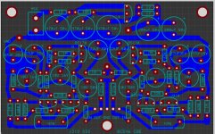
I've ordered bs170 and bf862, better input caps, and made a board to try out.
while waiting I used closest parts I have and it works at least,
2n7000 for the bs170 and J310 for BF862, Followed post #37 schematic.
The plan is to use a printer supply for now and try a linear supply later.
the J310 is not set up right as gain is unity, will try other values tomorrow.
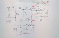
with R12 of 440R the gain is 3.5x but current goes from 12.5ma to 19ma using 35V bench supply.
I would like to find a use for those J310's as I have a few..
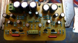
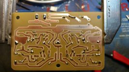
one person already made fun of my crooked 1R jumper so feel free to also
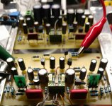
so far this is what I came up with following Juma's example.
while waiting I used closest parts I have and it works at least,
2n7000 for the bs170 and J310 for BF862, Followed post #37 schematic.
The plan is to use a printer supply for now and try a linear supply later.
the J310 is not set up right as gain is unity, will try other values tomorrow.
with R12 of 440R the gain is 3.5x but current goes from 12.5ma to 19ma using 35V bench supply.
I would like to find a use for those J310's as I have a few..
one person already made fun of my crooked 1R jumper so feel free to also
so far this is what I came up with following Juma's example.
Attachments
To set the J310's Id to 10-12mA you'll have to change R2 to 120-180 R, depending on its Idss.
I made this for BF862 which differs a lot (low Vp, high gm...). Try some load line optimization, but that will change the rest of the circuit a lot.
Based on previous experiences I'd say that you can expect some sonical dullnes/murkiness with J310 in this arrangement, but see if you can improve that by moving the operating point to a more linear region of the transfer curve ...
Thanks Juma for all you contribute here. Always interested in what you say and do.
I will build a new one with the correct parts when they get here.
This practice one is much closer now I believe, and the gain is 6.5x
Who knows I might even like this but its far away from what you laid out.
I don't yet understand load line optimization, no worries I will keep reading "the sweet spot" and
staring at the curvy charts in the data sheets.
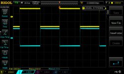
Here is what I measured, also noticed that even a DMM loads the circuit enough that numbers don't quite add up when you measure volts to ground (B C E) and compare to VBE
I will build a new one with the correct parts when they get here.
This practice one is much closer now I believe, and the gain is 6.5x
Who knows I might even like this but its far away from what you laid out.
I don't yet understand load line optimization, no worries I will keep reading "the sweet spot" and
staring at the curvy charts in the data sheets.
Here is what I measured, also noticed that even a DMM loads the circuit enough that numbers don't quite add up when you measure volts to ground (B C E) and compare to VBE
Attachments

did not get the BS170's yet should have come Saturday
but made one with BF862's and its MUCH better...
Perhaps the 2N7000 are fine in this role?
this one seems to need at least 34v to sound right.
( all my bench supply can do)
At 34.5v This is Nice! Time to order a 32v transformer..
Half the amps I made need some more gain for use with computers.
(don't know how to raise the gain enough with out messing them up)
This helps, Thanks
Attachments
- Home
- Amplifiers
- Pass Labs
- Gyrator loaded Son of ZV9/F3