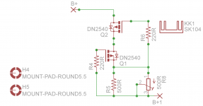
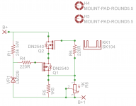
If I understand what was pointed out earlier, a decent CCS would be like that in the first schematic using depletion mode FETS DN2540. The second schematic would be a "improved version" by raising the gate voltage of the second FET, that would then require a larger sense resistor. In that case I chose a LM329 as an example which would require about 530R for the sense resistor for 15mA. I could use a LED which would have a lower required value. In either case, raising the gate voltage should result the output impedance increasing significantly by an order of magnitude if I understand the math.
Attachments
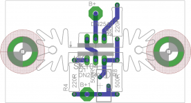
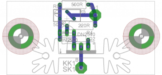
Ok, My math was off then as I calculated the first to have 10Meg and the second to be north of 100M. Will have to revist that. Here is a simple brd I came up with. I chose to use a small ohmite heatsink instead of the amp top plate with the idea of reducing capacitance. Not sure it makes a difference. I can actually keep the second FET off of the sink and possibly use a TO92 version if I could find one.
Attachments
The simpler first one will have a source impedance of something north of a gigohm with vanishingly low capacitance. I suspect you don't need to get any fancier.
And the source impedance of the improved version is about 25K plus the ESR of an LM329 (?) in parallel with a few gigohms.
 I see that now as well. Chaulk that up to learning.
 Please place gate stoppers (R6!) near to the gates as possible!Here is a simple brd
Hello All,
Now that the conversation has gone to the what if stage I will chime in. The amplifier looks to me like it has entered the no fault range and the conversation is academic. Excellent job SGregory.
More what if. The job of the power supply includes noise reduction and constant current to minimize mu, rp and gm of the tube. This minimizes distortion from the tube. It does not appear that there will be a big difference between tube and JFET amplifiers with the bolt on aftermarket CCS.
The rounding of the square waves is more a bandwidth thing than anything else. To get the level of performance shown the amplifier is already operating into the RF bandwidth. With that said what is the limiting item? Is it the CCS or the voltage regulator, both?
If you would, test the amplifier without the CCS gyrator stuff put a resistor in its’ place. The square wave performance may improve or not. Something is slewing and rounding the leading edge.
One added note, the noise floor of the 12B4 is surprisingly low.
DT
All just for fun!
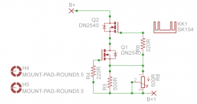
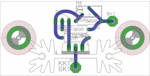
Here is a better version using the TO92 version for Q1. Q2 is stil TO220. Gate stoppers are now right on fet gates.
Symbol in schematic is now correct as well.
If it looks good then I will make a couple of these and test it. If it works as planned then I will redo the 12b4 board with this installed.
These little single boards will go in as the load for the input tube on my OPUS if they work.
DT, I will incorporate an easy means to isolate the load and install a load resistor in the CCS version so we can do your test. And not all of my 12b4's are that quiet.
Attachments
Last edited:
Here is a better version using the TO92 version for Q1. Q2 is stil TO220. Gate stoppers are now right on fet gates.
Symbol in schematic is now correct as well.
If it looks good then I will make a couple of these and test it. If it works as planned then I will redo the 12b4 board with this installed.
These little single boards will go in as the load for the input tube on my OPUS if they work.
Circuit looks good. For thermal stability try for a little distance between Q1 and Q2. Not heating Q1 cuts down the drift a little.
For increasing the bias on the Q1 the best bias supply I've found for use in CCS's is a cascode of LND150's feeding a resistor bypassed with a cap. In this instance the cascode is important for 2 reasons. First is minimizing the bypass leakage of the bias supply in parallel with the main CCS. Second is thermal isolation. A single LND150 program current with the power dissipated as the applied voltage changes. A cascode of LND150's does not show voltage dependent current changes. I use this circuit in the self bias CCS, the amplifier modules and the Swensen derived linear voltage regulator.
AudioTester- Yep, I forgot that you don't get the measurements when opening a *.cur file. The best I've come up with so far is to copy the on screen measurements, paste into notepad, edit the data so it's on a single line, then paste the edited data into the *.cur comment field. When the *.cur file is opened later you can copy the data to notepad and re arrange the data to your liking. Capture the screen from AudioTester and paste into your favorite graphics program. Then copy and paste the text from Notepad into the graphics file. A pain in the *** but the results are good.
To cut down on the amount of data presented in the on screen readout you can un-select "details" and only show data for the channel that you are going to put into the *.cur file.
Here is a revised pcboard with better spacing for less thermal transfer to Q1.
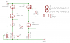
For grins and giggles, I played with Gary's suggestion with the LND150's and attached the schematic. C1 should be somewhere around 47 to 100uF. Designed for 15mA of current I calculate a 20 fold increase in impedance. Is my math correct? I do like the slow turn on feature.
For grins and giggles, I played with Gary's suggestion with the LND150's and attached the schematic. C1 should be somewhere around 47 to 100uF. Designed for 15mA of current I calculate a 20 fold increase in impedance. Is my math correct? I do like the slow turn on feature.
Attachments
- Status
- This old topic is closed. If you want to reopen this topic, contact a moderator using the "Report Post" button.
- Home
- Amplifiers
- Tubes / Valves
- Gyrator Loaded 12b4A: The Latest Version.