From a project I did a long time ago I've got some transformers left. A PT with 350 Vct @ 400mA + filament and bias taps and an OT of around 4k to 8 Ohm. They were initially intended for a push pull EL34 guitar amp and I plan on using them that way again, in a very different this time though.
Design goes were:
- Use what you have: Transformers, bread and butter tubes, etc. to keep the costs down;
- switchable input levels so the amp can be used with pedals in front (essentially effects return) or with line level (guitar preamp out);
- Modern flavour ala Diezel power amps: inductor based resonance control and wide band presence.
I'll be using MOSFET source followers to drive the power tubes. I've got very good experience with that in HIFI amps and the total absence of blocking distortion is a plus for this kind of amp (this will not be a bedroom practice amp).
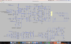
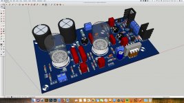
Below is the schematic of the proposed amp. I can't spot any mistakes, but I usually make them though. I'm currently designing the PCB's needed and am also powering on the power supply.
Design goes were:
- Use what you have: Transformers, bread and butter tubes, etc. to keep the costs down;
- switchable input levels so the amp can be used with pedals in front (essentially effects return) or with line level (guitar preamp out);
- Modern flavour ala Diezel power amps: inductor based resonance control and wide band presence.
I'll be using MOSFET source followers to drive the power tubes. I've got very good experience with that in HIFI amps and the total absence of blocking distortion is a plus for this kind of amp (this will not be a bedroom practice amp).
Below is the schematic of the proposed amp. I can't spot any mistakes, but I usually make them though. I'm currently designing the PCB's needed and am also powering on the power supply.
Attachments
That looks nice. Thanks for sharing. I have more questions than answers...
1) The current mirror sourcing for the MOSFET followers is fancy enough I would presume comes from the hifi world. How does that benefit a guitar amp? (I’m not suggesting it doesn’t; I’d just like to learn).
2) The +160 looks regulated. The -160 does not. Am I missing something, or is that an alternative to unbalanced phase-splitter resistors?
3) I am probably not agile in reading LTSpice models and transposing in my head to a physical connection...but I’m scratching my head at where I expect an output transformer...well, since you’re simulating it, I get that you need a model...it looks kind of like a solid state amp output (Zobel?) network...so I went back to look some more...a little confused. Your 50 Hz signal sources cued me into your distant geographical location...
Thanks
I would presume comes from the hifi world. How does that benefit a guitar amp
The source followers directly driving the output tube grids eliminate blocking distortion (AKA farting out). Using a CCS (chip or BJT pair) instead of a simple resistor on the source offers some advantages, the main one being elimination of the filtering / regulation requirements on the negative mosfet supply.
The +160 looks regulated. The -160 does not. Am I missing something, or is that an alternative to unbalanced phase-splitter resistors?
Actually the positive supply doesn't need regulation either since the PSRR of a follower is very high. In the HiFi world, one would regulate the grid bias supply AND the output screen grid supply, or neither. In the guitar amp world, active regulation is rare....unless you count the VVR's used for power reduction, most of which are not really regulators.
since you’re simulating it, I get that you need a model...it looks kind of like a solid state amp output (Zobel?) network...so I went back to look some more...a little confused.
We don't know what's inside the yellow box, I assume a real OPT model (I just use coupled inductors like shown for the power transformers). The stuff on the right of the yellow box is a speaker emulation model.
Thanks George for answering the questions. I'd like to add a bit more to the points you made.
1) The followers are a low load to the preceding phase inverter. The high local feedback of a CCS'd source follower keeps capacitances in the MOSFETs down, so the 12AX7 phase splitter can take a walk in the park on a Sunday morning driving the output tubes to clipping and beyond. Add to that the very low output impedance of the MOSFETs and low reverse transfer capacitance and you indeed have a HIFI worthy driver stage (IMHO).
Keep in mind, HIFI is essentially a goal. I don't want the output stage to behave like a typical Fender or Marshall output stage would.
2) The bias voltage is not regulated. I'd have to regulate the screens of the output tubes too if I would, otherwise bias would drift considerably when the mains voltage is varying.
The + line is regulated not because I need low ripple perse (although it doesn't hurt). The - line has highish impedance, but there will not be much current draw in any condition I could imagine. The + line however needs to deliver some current in instances where the is grid current in the output tubes. The goal of regulation was to provide a low impedance supply to the MOSFETs in that case so the voltage keeps constant and the voltage over the MOSFETs stays high enough to keep capacitances of them down to low levels.
I must admit: probably over-engineered. Other than complexity I see no big flaw in regulating. Unless I'm missing something, my knowledge is certainly not endless.
3) The yellow box is a generic 4k output transformer. The model contains data for the inductors, resistance of the inductors and coupling factor between the inductors. The data is not shown in this picture: all data was stripped in this screen shot.
Now that I'm thinking about the inherently good PSRR of a CCS'd source follower. Do you think I could get away with something simple like a bridge rectifier and just one filtering cap per side for the +/- 160V lines George? Doesn't save a lot of money, but everything helps.
I've got another question. I'm planning to use a small Icon transformer as an inductor for the resonance network. The 42TM013-RC (1k to 8 Ohm) is sometimes used in wahwah pedals because the primary side has about 500mH inductance. IIRC that translates to 1k Ohm at 300 Hz. Am I right to assume that a transformer with a 2k secondary would then measure 1H? The 42TM002-RC is a different set of inductors at the same size. More inductance would certainly be welcome to keep the impedance peak of the resonance network narrow.
1) Can I power the MOSFETS and bias with a simple C-filter supply? So no CRC, just one capacitor.
2) Can I use a 2k->10k transformer (Xicon 42TM002-RC) primary as a 1H inductor for the resonance circuit?
2) It's a three-dollar experiment. No simple prediction. Buy it, try it. Me, I'd get several models different Zs; if one misses, another may hit your mark.
1) Probably; but it isn't a big current and another R-C is not a big expense until you put this in mass production. Anyway, isn't the *point* "overkill"? You sure don't need to MOSFETs to make a hellufa guitar amp. So why stop there?
The goal of regulation was to provide a low impedance supply.... the voltage over the MOSFETs stays high enough to keep capacitances....down.
Can I power the MOSFETS and bias with a simple C-filter supply? So no CRC, just one capacitor.
I am currently working on a stereo HiFi amp that runs KT88's on about 500 volts. I use an LTP PI made with a 6CG7 driving mosfets to feed the grids of the KT88's. The current test amp uses a line isolation transformer (120 - 0 - 120 VAC), a silicon bridge rectifier, and a single 220 uF cap to generate +/- 160 volts for the mosfets. There is no regulation on either the positive or negative supplies.
The amp makes extremely low distortion numbers as-is (0.2% at 1 W, 1.6% at 70 W). Total hum across the speaker with the input disconnected is 700 microvolts! This says that regulation isn't needed, and the single big cap will likely work. I will try a CRC next just to see if I can make the PCB a bit smaller. It is not a "guitar amp", but I will play my guitar through it.....and the synthesizer, and the digital drum set, and......
That whole amp design is here.
Tubelab Universal Driver Board, 2015 version
Can I use a 2k->10k transformer (Xicon 42TM002-RC) primary as a 1H inductor
There is no real way to know the inductance of a transformer winding that isn't specified without measuring it. It may be wound with a different core, or a different wire size than the one you measured. The transformer winding will also likely have a lower "Q" that an inductor designed for audio, causing the filter to exhibit a wider bandwidth than a real inductor. It still could be useful in your circuit, but may not work like the amp you were looking at. You could also use two of the 500 mH units in series.
I once got the brilliant idea of sticking a tone stack in the feedback loop with a volume knob. It led to all sorts of cool tonal possibilities including full on oscillation at about 80 watts. I will explore this again someday on an amp of much lower power. If you go this way......proceed with caution....and a speaker that won't blow up!
PRR, you are right! It is a cheap experiment. I should be able to make a PCB that can be wired for usage of the primary or secondary side of it. I was just thinking: specified reactance is regularly (IIRC) measured at 300 Hz. a 2k primary (with open secondary) must thus be about 1.1 H. Which would be great. I can't find any other inductors with a high inductance but low resistance. Multiple wahwah inductors would work, but that's an expensive solution.
I'm planning to use an isolation transformer for the bias and MOSFETS. The last drawing I made is essentially the setup you talk about. I think 700uV will not be a problem, even through a 4x12 cabinet with 100dB/m speakers. Simulation suggests that there is much more to be gained by properly matching the output tubes, a well made OT and careful symmetric bias adjustment.
I'm planning to use an isolation transformer for the bias and MOSFETS. The last drawing I made is essentially the setup you talk about. I think 700uV will not be a problem, even through a 4x12 cabinet with 100dB/m speakers. Simulation suggests that there is much more to be gained by properly matching the output tubes, a well made OT and careful symmetric bias adjustment.
George, I recently read most of the pages about the AB2 6L6 amp by Chris and your efforts concerning the driver stage. The driver I propose is able to drive the grids positive, mainly to get rid of blocking distortion. However, I could squeeze more output out of a pair of 6550's, but then I need to lower the screen voltage, right?
How can I implement that in the design? I've got a Marshall 1987 with a series regulator for the screens. The regulator is right behind the choke, in parallel with the rest of the power supply. Done this way, because it was the easiest way with the existing power supply. That solution seems overkill for this amp though.
How can I implement that in the design? I've got a Marshall 1987 with a series regulator for the screens. The regulator is right behind the choke, in parallel with the rest of the power supply. Done this way, because it was the easiest way with the existing power supply. That solution seems overkill for this amp though.
Thanks, George & Rootz.
Upon asking an engineer at a transformer company some questions about measuring or estimating output transformer inductance (and getting wildly varying results depending on what equipment), I was told to not bother trying to measure iron core inductances at test signal levels drastically different from the intended operating conditions...otherwise all bets are off...especially with an automated instrument that decides what puny signal and frequency it deems appropriate. He recommended an incremental inductance meter and all the bells and whistles that needs. Not today.
I still check with a variac for a sanity check on turns ratio. When I compare inductance ratio (with whatever inductance meter or bridge I can borrow) of primaries and secondaries against turns ratio (which I then square to get Z ratio, being proportional to L ratio), I get surprisingly different numbers. I realize both methods are cutting corners in different ways (ignoring magnetizing current/losses for the voltage method, and luck of the draw with inductance neasurements). The difference is enough to feel like the measurements are so inaccurate I can’t bet on them. But it does help figure out ballpark values and which leads are which for mystery transformers...
I’m not sure I really want a General Radio 1633A + oscillator power amp. That’s a whole lot of bench space. But at least I can now identify one in a lineup so if I ever find a surplus one I can give it a second thought.
My mother liked to say ‘a little knowledge can be dangerous’...but I haven’t found that to be a deterrent (how would I know, anyway?)
..I was told to not bother trying to measure iron core inductances at test signal levels drastically different from the intended operating conditions...
OR frequency. Iron cores are squirrely every which way.
Just build the thing you want to build, on breadboard rather than committing to PCB, then try it. Does the "Mids" (or whatever) go up and down nice? Does it get gnarly at high level? You can maybe trim the frequency by changing the cap some. More by changing the network impedance so the Q does not go far off. You can trim a gnarl at high level by working at a lower level. But if you commit a complete and completely untested design to PCB, it will probably not work right. ALL audio can be bench-tested on copper tacks in a board, a proto-board, or other ad-hoc wiring system.
I’d rather breadboard it first of course. Problem is I’m not sure how with a circuit as complex as this one.
Hi Rootz, is there any design reason for:
- the lowish 100k input grid leak
- the R44/C20
- the R41/C12 and R42/C13
- the high screen voltage (488V ?)
- the R17/C17 and R38/C23 (have you done quasimodo like testing to get those values?)
- are you using a standard full-wave rectifier for the 350-0-350 main winding? You may need 2x UF4007 in series for each rectifier to give some margin.
- how damped is your plate-screen supply inductor?
- are you going to try and roll off the bass end below instrument fundamental frequency, or let all the bumps and thumps pass through for your OT and speakers to enjoy ?
- are you planning to run the EL34's at max design idle power on that pcb, and with its nearby parts?
Last edited:
Hi Rootz, is there any design reason for:
- the lowish 100k input grid leak
- the R44/C20
- the R41/C12 and R42/C13
- the high screen voltage (488V ?)
- the R17/C17 and R38/C23 (have you done quasimodo like testing to get those values?)
- are you using a standard full-wave rectifier for the 350-0-350 main winding? You may need 2x UF4007 in series for each rectifier to give some margin.
- how damped is your plate-screen supply inductor?
- are you going to try and roll off the bass end below instrument fundamental frequency, or let all the bumps and thumps pass through for your OT and speakers to enjoy ?
- are you planning to run the EL34's at max design idle power on that pcb, and with its nearby parts?
- You mean the potmeter? I try to keep series grid resistance as low as I can to keep the Miller effect low. -3 dB at 20kHz or even 10kHz is fine of course;
- High frequency stability. Might not use it, but measurements have to tell;
- Idem for the snubber on the OT;
- Screen voltage should be fine with EL34's, but I'd like to be able to lower the screen voltage to switch to e.g. 6550's. Not sure actually how to do that. Will draw some ideas up;
- R17/C17 not tested, but a rough guesstimate. Haven't worked with the quasimodo test jig before. Just did some reading about it. Looks like I've got some more learning to do about power supplies (in general really);
- Grabbed the first model I could find in ltspice for the diodes. Been using BYV26e's (1000V/1A) in an amp with a 300-0-300 V supply. That's in a full wave rectifier. I thought that was not needed in a voltage doubler bridge??;
- Plate screen supply doesn't look well damped. Not critically damped if you ask me. Swings up and down a couple of times. How to improve?;
- Not sure if I need to roll of bass in the power amp. The pre amp will have some considerable roll off. It is easy enough though. I can lower the first cap to 1nF for example and raise the -3dB point a lot;
- The power tubes will not be on the PCB where the other components reside. If I'm going to use a PCB for the power tube sockets, it will be just for them and the gris and screen resistors. I happen to have three PCB's for just that and some PCB sockets lying around here. Why not use em (and hope for the best)?
If I might sound cocky: I'm trying not to sound like and be it! If you have any recommendations, I'm more than happy to look into them.
Good to see the effort you are putting in - go for it ")
Just throwing out some queries to appreciate where you were coming from - makes for a more interesting thread for most of us I'd hope.
Most guitars have tone pots and pickups set up for circa 1Meg loading - there are a few good design assessments on the web of how that sort of works the best. Not an issue if the amp is meant for pedal outputs, or if you provide another input socket that switches the loading to 1Meg, or vice-versa make one socket switch to 100k.
Sorry for confusion about the pcb, I missed the ECC83 markings.
Above about 280-300VAC for a full-wave capacitor input filter configuration, the margin for a single 1kV PIV diode starts to get thin, and using 2x in series is an easy way to make bullet-proof.
Guitar amps are often pushed to 11 on the volume pot, whether that is to push preamp/PI valves, or output stage valves, or speakers, or your ears, in to a different sound zone. And input signals can have long continuous max levels due to speaker-guitar feedback. The screen dissipation and screen supply parts may need some thought, especially if you can drive the input grids easily beyond 0V. Some amps tee off the screen supply, and sag/decouple it separately - which allows the other preamp rails to not sag in sympathy, but then some amps purposefully aim to sag the preamp stages - the joys of interaction and what 'tone' control you have between your ears and brain (ie. everyone in guitar land has a different view on what sounds better).
Thanks Trobbins. Your efforts are more than enough to keep my brain going, which is part of the fun of designing and building for me.
I could keep the input impedance on the first tube much higher by relocating the volume control after the first stage. Mesa does something like that in their 2:90. It would make the amp a bit more versatile at the cost of an extra coupling cap (outside the feedback path).
I've got some amps that sag, a JTM45 and JTM50. Currently a 1973 Super Bass on the work bench. That one doesn't sag nearly as much. Very different power supplies on all of them. This new power amp will be used with a preamp or pedals that provide all the compression I could ever use if needed. No need for a sagging PSU.
Will investigate those diodes further. See what calculation reveals.
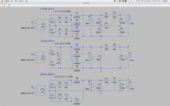
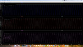
Some simulations I promised, representing the voltage over D1, D5 and D9. In both bridge rectifiers the diodes see max the peak voltage of the full secondary, so 500V. Full wave is essentially the same, but as the secondary puts out double the voltage compared to the top two transformers, they will see 700*sqrt2 when loaded and even more unloaded. That's over 1kV, so there is a need to double the diodes.
FWIW: Marshall uses a 1n4007 bridge in their 100W 1959 super lead. Single diodes. Voltages are roughly the same.
The margin get really thin with a full wave rectifier indeed. Marshall used triple series diodes in the JTM45/100 IIRC.
If I'm failing to see the point in doubling, correct me (again) please. In the mean time I'll post some proposals for the screen supply.
Attachments
- Status
- This old topic is closed. If you want to reopen this topic, contact a moderator using the "Report Post" button.
- Home
- Live Sound
- Instruments and Amps
- Guitar power amp proposal