Hi All,
So I've decided to build an instrument/guitar level (-20db) to line level (-10db) preamp for a recording interface. I want to use a high end op-amp to do the job, and through forum surfing came across the OPA134 as a potential candidate to do the job. I'm using a schematic for a TL071 as reference (pictured below) since this is my first preamp build. I have a couple questions regarding my design:
1. Does the supply voltage affect the circuit other than defining the range of the input/output voltage? Guitar signals use very low voltage (passive pickups are anywhere from 0.1V to 1.0V, active up to 1.75V), so I guess lowest supply I could use would be a 9V supply, since the pickup + gain shouldn't be more than (1.75V + (1+220k/100k) = 5V)?
2. Do I need a completely different design than the one pictured? Or is this a good reference to use? I know different op-amps call for different combinations and placements of resistors and capacitors, but I'm having trouble finding a similar project with an op amp in the OPA family.
3. If I wanted to put a gain knob on the op-amp, would this be achieved by putting a pot in place of R2, with the value of the pot being 220K?
I'm going to start putting together a schematic and order some parts to mess around with, but any guidance is greatly appreciated!
.
Power supply voltage has nothing to do with signal (audio) voltage. The power supply only runs the amp, it doesn't interact with the audio signal. Or that is, it doesn't interact unless the audio input voltage approaches the power supply voltage, see next paragraph.
Broadly speaking, an audio input voltage can come within 2 volts of the power supply voltage. That is, if your power supply voltage is +/- 16 volts (for instance), then an audio input up to 14 volts is OK. Running a 9 volt single supply (still for instance), maximum input would be 2.5 volts.
(It's 2.5 volts because the 9 volts is actually divided into two voltages of 4.5 volts each to run the amp.)
If you play heavy metal, the output of a guitar pickup can be several volts--but probably not 14 volts. Same for piezo pickups.
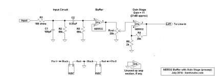
The TL072 is not used for hi-fi. I suggest using the NE5532 (about 50 cents apiece on Bay). The NE5532 was the top of the line for many years, every studio in the world had and has dozens or hundreds of them in their boards and amps. Recently developed chips like the LM4562 (about $5), or OPA134, do have better specs on paper, but I personally don't hear that the paper specs make any real world difference.
Getting to cases, what you need is a buffer. A buffer has extremely high input impedance (100s of megohms), so in effect it "looks at" an audio input source (guitar pickup), but does not affect that source in any way. This is exactly what you want with audio inputs.
I happen to have a schematic on hand, so I'm posting it.
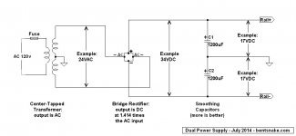
I'm also posting a representative (only that) dual power supply schematic. Please give serious thought to using a dual power supply, as opposed to a single supply, because dual power supplies make amp circuits simpler. The NE5532 runs happily at around +/- 16 volts, which you get from a 24 volt center tapped transformer.
Some circuit notes follow. Especially notice at the end for guitar pickups.
Hope this might be of some help.
===
Circuit notes:
R1 is overcurrent protection for the NE5532, and also guards against oscillation.
C1 shunts radio frequency energy to ground. Both stage and studio environments can be expected to have high levels of radio frequencies.
R2 is a load resistor, put there because you usually don't know what the input signal is going to come from. By providing a current path to ground R2 ensures that there will be voltage at the input side of C1. R2 in parallel with R3 sets the input impedance, which here is about 20k.
(If R2 is not present, then the value of R3 is the input impedance.)
C2 and R3: C2 blocks DC, and with R3 forms a high-pass filter, also called a bass rolloff filter. Here the rolloff starts at just over 20 Hz.
U1a (1/2 of a NE5532) is a buffer. It's characteristic of op amps that connected this way they have unity gain, extremely high input impedance, and extremely low output impedance, all of which is ideal for audio inputs.
Rvol is the volume control. The value can actually be anything from 2k (no lower) on up.
U2b (the other half of an NE5532) is the gain stage, which here is arbitrarily set at a gain of 11 (21 dB). Gain can be anything theoretically, but keep it to 20 or so in the real world. The formula is simply R4 divided by R5, and add 1. That is:
Gain = R4/R5 + 1
For preference, leave R5 at about 2k and adjust R4. Higher resistance for R4 = more gain. R5 no lower than 1k, if you must.
The output is low impedance, and should be suitable for the line-in input of a mixer, preamp, or amp.
NOTE: The 20k input impedance shown here is much too low for instrument pickups, such as on a guitar or bass. It will work, but not really well. To be strictly correct with an instrument pickup, change both R2 and R3 to 1meg, for a 0.5meg input impedance. Change C2 to 0.068uF
Caution: 1meg is a very high value in audio terms, and noise problems can multiply. Keep leads short, use shielded wire, and ground everything, including the body of pots (Rvol).
.
Power supply voltage has nothing to do with signal (audio) voltage. The power supply only runs the amp, it doesn't interact with the audio signal. Or that is, it doesn't interact unless the audio input voltage approaches the power supply voltage, see next paragraph.
Broadly speaking, an audio input voltage can come within 2 volts of the power supply voltage. That is, if your power supply voltage is +/- 16 volts (for instance), then an audio input up to 14 volts is OK. Running a 9 volt single supply (still for instance), maximum input would be 2.5 volts.
(It's 2.5 volts because the 9 volts is actually divided into two voltages of 4.5 volts each to run the amp.)
If you play heavy metal, the output of a guitar pickup can be several volts--but probably not 14 volts. Same for piezo pickups.
The TL072 is not used for hi-fi. I suggest using the NE5532 (about 50 cents apiece on Bay). The NE5532 was the top of the line for many years, every studio in the world had and has dozens or hundreds of them in their boards and amps. Recently developed chips like the LM4562 (about $5), or OPA134, do have better specs on paper, but I personally don't hear that the paper specs make any real world difference.
Getting to cases, what you need is a buffer. A buffer has extremely high input impedance (100s of megohms), so in effect it "looks at" an audio input source (guitar pickup), but does not affect that source in any way. This is exactly what you want with audio inputs.
I happen to have a schematic on hand, so I'm posting it.
I'm also posting a representative (only that) dual power supply schematic. Please give serious thought to using a dual power supply, as opposed to a single supply, because dual power supplies make amp circuits simpler. The NE5532 runs happily at around +/- 16 volts, which you get from a 24 volt center tapped transformer.
Some circuit notes follow. Especially notice at the end for guitar pickups.
Hope this might be of some help.
===
Circuit notes:
R1 is overcurrent protection for the NE5532, and also guards against oscillation.
C1 shunts radio frequency energy to ground. Both stage and studio environments can be expected to have high levels of radio frequencies.
R2 is a load resistor, put there because you usually don't know what the input signal is going to come from. By providing a current path to ground R2 ensures that there will be voltage at the input side of C1. R2 in parallel with R3 sets the input impedance, which here is about 20k.
(If R2 is not present, then the value of R3 is the input impedance.)
C2 and R3: C2 blocks DC, and with R3 forms a high-pass filter, also called a bass rolloff filter. Here the rolloff starts at just over 20 Hz.
U1a (1/2 of a NE5532) is a buffer. It's characteristic of op amps that connected this way they have unity gain, extremely high input impedance, and extremely low output impedance, all of which is ideal for audio inputs.
Rvol is the volume control. The value can actually be anything from 2k (no lower) on up.
U2b (the other half of an NE5532) is the gain stage, which here is arbitrarily set at a gain of 11 (21 dB). Gain can be anything theoretically, but keep it to 20 or so in the real world. The formula is simply R4 divided by R5, and add 1. That is:
Gain = R4/R5 + 1
For preference, leave R5 at about 2k and adjust R4. Higher resistance for R4 = more gain. R5 no lower than 1k, if you must.
The output is low impedance, and should be suitable for the line-in input of a mixer, preamp, or amp.
NOTE: The 20k input impedance shown here is much too low for instrument pickups, such as on a guitar or bass. It will work, but not really well. To be strictly correct with an instrument pickup, change both R2 and R3 to 1meg, for a 0.5meg input impedance. Change C2 to 0.068uF
Caution: 1meg is a very high value in audio terms, and noise problems can multiply. Keep leads short, use shielded wire, and ground everything, including the body of pots (Rvol).
.
Attachments
Last edited:
To be honest, I suggest the first schematic using TL071 is much better as guitar buffer. NE5534 is a superior choice when driven by lo impedance source - but they are a no-go as input stage of hi-impedance sources like magnetic guitar pickup. Due to the high noise current, the TL071 will by far outperform the NE5534 in this application.
Furthermore it is no good idea to load the PU with an input impedance of about 23kOhm, which kills any overtones yielding a muffling sound.
All in all, there is absolutely nothing bad with that simple TL071 input stage.
Just my 2c
Furthermore it is no good idea to load the PU with an input impedance of about 23kOhm, which kills any overtones yielding a muffling sound.
All in all, there is absolutely nothing bad with that simple TL071 input stage.
Just my 2c
.
Well...wait...hold everything.
I have to semi-agree with voltwide. The TL071 circuit shown would certainly work. Bolt it together just as shown, don't change a thing, and it will do the job for you. Just be sure to keep connecting leads as short as possible, those resistors are waaay up into funny-noises territory.
Those should have been the first words out of my mouth...keyboard. Then I should have said something like, "But you might not have the audio quality you want for a studio setup, and if not here's an alternative," or to that effect.
So questions of impedance (not a problem) aside, maybe I did overreact and make things complicated. My bad.
.
Last edited:
.
voltwide, you didn't read the circuit notes, did you? Nooo, you didn't. They might be of interest.
<< I suggest the first schematic using TL071 is much better as guitar buffer >>
The TL071 circuit shown is not a buffer, it's an amp. Two different animals entirely.
.
Whether you run the input amp at V=1 or V=3 does not really make the difference, g=3 is a good starter for a guitar input amp when powered by 9V.
I am in that business for decades. And your circuitry is much more complicated compared to the TL071 version, including the split supply, all that to no advantage, but with totally wrong input impedance and sub-optimal noise performance.
.
Well...wait...hold everything.
I have to semi-agree with voltwide. The TL071 circuit shown would certainly work. Bolt it together just as shown, don't change a thing, and it will do the job for you.
.
Thats it - don't waste your time with fiddling about with pre-Amps,
the sound of the guitar is at your fingertips
")
Thanks to the both of you for your help! Since this preamp is a smaller piece in a bigger picture, it's probably best that I not do too much fiddling and stick to the working schematic I have. That being said, if anyone else has a preamp schematic for an op amp in the OPA series, I'm all ears! One question I do have is what's the difference between a buffer and a preamp? If the buffer really does just "look at" the signal, then why's it used? To get high impedance on the input? Why can't I just do that with resistors? Sorry if these are dumb questions, I'm fairly new to op amps. And if this is just a buffer, and it's all I need to get a good clean guitar signal into my ADC, then what would a preamp be used for in place in another scenario? For tone?
Secondly, bentsnake mentioned that if I play a lot of metal, I'd be looking at a higher voltage. My understanding was that passive and active pickups have a collective range of about 0.1V to 1.75V. If that's the case, I should be okay in using a 5V line, correct? The reason I'm asking is because my project currently runs off of a 5V dc supply, and while I could definitely use an external 9V supply and then later integrate a 9V supply line into my project, it'd definitely be easier to just use 5V. Obviously I want a full range for guitar input, so if 5V wont cut it, then I'll use 9.
Thanks again to the both of you!
Pat
Guitar output level might vary over a wide range of voltage.
It depends on
-the pickups
-distance between pickups and strings
-thickness of strings
-the way you strum
I measured my strat and the most I could get out of it was about 2Vpeak-to-peak.
A humbucker will deliver even more.
If your supply is 5V, a buffer with FET-input and rail-to-rail input and output may be the best choice.
Anyway it is a good idea to measure with an oscilloscope the voltage you get out of your instrument.
.
<< bentsnake mentioned that if I play a lot of metal, I'd be looking at a higher voltage. My understanding was that passive and active pickups have a collective range of about 0.1V to 1.75V >>
My mouth ran faster than my brain, sorry. I don't know the actual output of your pickups. I do know that the harder you hit it, the higher the output voltage, but I can't quote a real-world value.
.
'
<< what's the difference between a buffer and a preamp? If the buffer really does just "look at" the signal, then why's it used? To get high impedance on the input? Why can't I just do that with resistors? >>
OK I think I see the problem. First I'm going to quote what I wrote before, then I'm going to modify it.
"A buffer has extremely high input impedance (100s of megohms), so in effect it "looks at" an audio input source (guitar pickup), but does not affect that source in any way. This is exactly what you want with audio inputs...U1a (1/2 of a NE5532) is a buffer. It's characteristic of op amps that connected this way they have unity gain, extremely high input impedance, and extremely low output impedance, all of which is ideal for audio inputs."
Here's what I probably should have said:
"...[a buffer] "looks at" an audio input, and reproduces the audio input at its output. It does this without affecting the audio input source in any way."
For further clarity (I hope), I'm breaking your question down:
<< If the buffer really does just "look at" the signal, then why's it used? To get high impedance on the input? >>
Yes exactly, to get high impedance at the input, and only for that reason. But note:
Why high impedance? And what's this "affecting the audio input source" mean?
Your guitar pickup puts out 1 or 2 volts probably (I don't really know), but it puts out only a very small amperage. "Volts" is the electrical pressure that makes amps flow, but "amps" is the stuff of electricity itself, amps is what does the work. "Amperage" and "current" are the same thing.
If your guitar is connected to a low impedance (a low resistance), then too much current can and will flow.The result will be that the overloaded pickups won't reproduce your playing accurately, there will be distortion. This is the "effect on the audio input source" that you want to avoid.
But connected to a high impedance, very little current flows, the pickups work as they were designed to work, and things sound right.
Back to buffers. But why a buffer with an NE5532, but not with a TL071?
Because a TL071 is already a high impedance device, that's how it's made. It already has an input impedance in the megs of ohms (millions).
But an NE5532 is not made that way, it's a medium-impedance device, with input impedance in the tens of kilohms (thousands). So all by itself it has too little resistance, and will overload your pickups.
But not when it's wired up as a buffer. Connected as a buffer the NE5532 also has input impedance in the megohm range, so your pickups work as intended. And--and this is the reason I brought it up in the first place--the NE5532 has less distortion and better tonal quality. Although...admittedly "better tonal quality" is in the ear of the beholder.
Whew. Any of this making sense?
.
Last edited:
Wow, thanks so much for that reply!! All of it made sense, luckily for me, the concept of impedance is familiar from school (just graduated) so I understood all of that very well. The last question I had regarding that is why can't you just use resistors instead of the buffer to raise the impedance? (using 1M ohm resistors, etc). Or do you need both?
And in regards to the voltage of the guitar, I'm looking to make this pedal not just for one guitar, but for any kinds of guitars and any player. So I want to take the absolute maximum voltage that could be produced into account... I guess I should consider 9V or even 12V then. This is fine with me, because most interfaces of this sort run off of 12V, so I suppose I'd have to make the switch eventually!
But now I know why the Hi Impedance specs on op-amps are so important for my specific application... Cuts out the need for a buffer, correct?
So since bentsnake said to be cautious with the length of my resistor leads due to noise, does this mean that I should skip the breadboard stage and go right to perf board to eliminate more noise?
You guys are awesome... I purchased a couple TL072s and will hopefully get them at some point next week...
Pat
Pattobrien,
You might like to have a read of this thread, and my suggested circuit
http://www.diyaudio.com/forums/inst...d-unbalanced-line-receiver-3.html#post3817648
See also post #32.
regards,
Paul Bysouth
You might like to have a read of this thread, and my suggested circuit
http://www.diyaudio.com/forums/inst...d-unbalanced-line-receiver-3.html#post3817648
See also post #32.
regards,
Paul Bysouth
.
<< The last question I had regarding that is why can't you just use resistors instead of the buffer to raise the impedance? >>
Whoops, I missed that one. Very good question.
The answer is that you do set input impedance with resistors. Noting that you wouldn't speak of raising or lowering impedance with resistors, you speak of setting it, that is, you create it.
Somebody needs to study up on how op amp circuits work, emphasis on input circuits. But speaking very broadly, the resistor closest to an op amp sets the input impedance. Or if there are several resistors, then their parallel value is the circuit's input impedance.
VERY IMPORTANT: This "speaking very broadly" is so broad as to be almost meaningless. Consider that we're speaking only of this circuit.
Along with that, don't mix apples and oranges. Amplifiers are one thing, input circuits are another thing. Importantly, realize that buffers are amplifiers. They're a special case of amplifiers with a gain of unity, and you'd never say amp, you'd always say buffer, but still buffers are amplifiers.
All of which evolves into the following, which is critical, it's the nexus, the very heart of the matter:
The impedance of an input circuit is one thing, the impedance of an op amp is another thing. They have nothing to do with each other.
The factory sets the input impedance of the op amp, you set the impedance of your input circuit. And now it falls to you to make your circuit work with their op amp.
Happily, you don't have to get an engineering degree to deal with this. Around here we let somebody else do the math. What we do is reach into our bag of tricks and pull out a rule of thumb.
We take it as a given that we need 1meg or higher input impedance for a guitar pickup (rule of thumb). So we set the impedance of our input circuit to that value simply by choosing that value of resistor(s). So now we need to feed the op amp.
But we have to follow the "times 10" rule of thumb. That is, whatever a circuit's impedance might be (in this case 1meg), the following circuit must have an input impedance of 10 times that or better. In this case the "following circuit" is an op amp, so that op amp must have at least 10meg input impedance.
The TL071 does. In fact, it has an input impedance of about ten million meg. And this very high input impedance is why it's so often chosen for use in guitar amps (the only reason, as far as I know).
But what about the NE5532? Fail. It has a worst-case input impedance of about 30k, which is far too low. Low resistance means high current flow, in this case too high, so the preceding circuits will be overloaded and distort.
That is, unless I have something else in my bag of tricks? It just so happens I do. I reach in and pull out, tada, a buffer, and this deceptively simple little circuit changes everything. The NE5532 now has a multi-meg input impedance too. How many megs, exactly? I don't know. At one time I tried to calculate it, but my dime store calculator ran out of zeros.
All of this applies equally to any circuit. But CD players, iPods, whatever always have low impedance outputs (including headphone outputs), so generally an input circuit of around 20k impedance is fine.
.
.
<< ...be cautious with the length of my resistor leads due to noise, does this mean that I should skip the breadboard stage and go right to perf board to eliminate more noise? >>
No, not at all. Actually this keeping leads as short as possible applies to all circuits. But high impedance circuits are especially susceptible to noise, so just be aware of the fact.
.
.
<< I'm looking to make this pedal not just for one guitar, but for any kinds of guitars and any player. So I want to take the absolute maximum voltage that could be produced into account... I guess I should consider 9V or even 12V then. This is fine with me, because most interfaces of this sort run off of 12V, so I suppose I'd have to make the switch eventually! >>
Pedals very commonly run on a 9 volt battery. I can't say it's universal, but I know a whole lot of them run that way.
.
.
<< ...now I know why the Hi Impedance specs on op-amps are so important for my specific application... Cuts out the need for a buffer, correct? >>
100% correct. Although in defense of those of us who use buffers I'm going to say that the total cost is about 50 cents, and the benefit is that a buffer absolutely, positively, no-questions-asked separates input from output, which is the ideal state for audio circuits. Actually for all circuits, as far as I know.
.
Last edited:
 The best place for this would be over in Instruments & Amps.. So I'll move it there. Should be some people over there with some insights you'll find helpful.
Build the first (TL071) preamp/buffer, which has the proper gain and impedance.
If gain is not enough for your pickups (say single coil instead of humbuckers) you can lower R1 to 47K to double the gain.
The second (NE5532) schematic has a useless "buffer".
Why?
Because as shown it has unity gain (duh!) *and* totally inadequate 23K input impedance.
FWIW you might connect the guitar straight to the 20K input pot.
- Status
- This old topic is closed. If you want to reopen this topic, contact a moderator using the "Report Post" button.
- Home
- Live Sound
- Instruments and Amps
- Guitar Level to Line Level Hi-Quality Preamp