What I don't understand is how this connection can make it into a triode that can take higher voltages and why the grid drive becomes +ve?
Think of geometry and strength of fields inside of the tube. Find some basic explanations in tube books to understand it better: how paramaters depend on distance between grid and cathode, grid and anode, and what happens when in shorter distance from cathode one more positively charged grid is added.
ok, will do that... but be prepared for more questions.... heheheh
If you are Doctor you should know well about fibrillation...
")
Usually 1'st car people buy cheap and used. Why? To get experience on mistakes...
What I don't understand is how this connection can make it into a triode that can take higher voltages and why the grid drive becomes +ve?
Think about typical output triode tube. It draws high anode current when the grid voltade is zero, even when the anode voltage is quite low.
The reason is that it's grid is formed by a sparse metal wire net only. In typical application of such triode, the anode current is controlled only to downward direction by applying negative voltage to the grid.
In a hi-mu triode like 811A the grid is constructed by a much more dense metal grid. Now when this kind of tube has zero grid voltage, the anode current is very low, because electrons can not easily get through the dense grid net to the anode, even when the anode voltage is quite high. Therefore this sort of tube reguires positive grid voltage to speed up the electrons so that sufficient anode current can flow.
So, in typical triode the negative grid voltage is required to restrict (and control) the anode current while in case of special hi-mu triode (zero-bias-triode) the positive grid voltage is required to accelerate (and thus control) the anode current.
How the pentode GU50 can become a hi-mu triode ?
A pentode has three grids between the cathode and anode. When these all (or only g1 and g2 ) are connected togeter, the very dense grid system is created. Therefore the operation is converted similar like the 811A hi-mu triode.
If you are Doctor you should know well about fibrillation...
Usually 1'st car people buy cheap and used. Why? To get experience on mistakes...
Hi,
was in response to thisok, will do that... but be prepared for more questions.... heheheh
Think of geometry and strength of fields inside of the tube. Find some basic explanations in tube books to understand it better: how paramaters depend on distance between grid and cathode, grid and anode, and what happens when in shorter distance from cathode one more positively charged grid is added.
So I do know about fibrillation and trying something simple before going advanced ;-)
Think about typical output triode tube. It draws high anode current when the grid voltade is zero, even when the anode voltage is quite low.
The reason is that it's grid is formed by a sparse metal wire net only. In typical application of such triode, the anode current is controlled only to downward direction by applying negative voltage to the grid.
In a hi-mu triode like 811A the grid is constructed by a much more dense metal grid. Now when this kind of tube has zero grid voltage, the anode current is very low, because electrons can not easily get through the dense grid net to the anode, even when the anode voltage is quite high. Therefore this sort of tube reguires positive grid voltage to speed up the electrons so that sufficient anode current can flow.
So, in typical triode the negative grid voltage is required to restrict (and control) the anode current while in case of special hi-mu triode (zero-bias-triode) the positive grid voltage is required to accelerate (and thus control) the anode current.
How the pentode GU50 can become a hi-mu triode ?
A pentode has three grids between the cathode and anode. When these all (or only g1 and g2 ) are connected togeter, the very dense grid system is created. Therefore the operation is converted similar like the 811A hi-mu triode.
Hi Arto,
Thanks for an incredible explanation. Better than any textbook of electronic theory.
Hi,
was in response to this
So I do know about fibrillation and trying something simple before going advanced ;-)
Sorry, I felt a burning urge to remind you again about lethal voltage and probable mistakes...
I wish you to be alive and live long happy life!
Sorry, I felt a burning urge to remind you again about lethal voltage and probable mistakes...
Ok. Noted.
Thanx my fren. Same to you too..I wish you to be alive and live long happy life!
Hi Guys,
I have made some test with GU50 triode mode and 100 ohms on G2. The max anode voltage tested was 450V/56ma and -70 Bias, and with 37v Rms G1 (1khz) max dissipation G2 grid was less than 1w.
I also made other tests with 420v and 430v 70ma and 65ma
In my next project I will choose the operating points for Gu50 B+ 430v 65ma -63v. This is pretty safetly for 3 tubes PP Gu50 with 2K OPT.
Hi Guys,
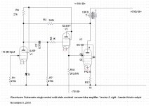
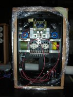
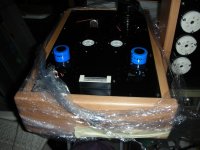
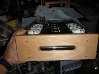
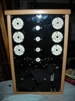
Sorry for delay but I have been very busy, the output trafo isa vanderveen toric version with cathode feedback. I am planning to finish the project until end of the current year, will see and then will post all the information. here some pics.
Sorry for delay but I have been very busy, the output trafo isa vanderveen toric version with cathode feedback. I am planning to finish the project until end of the current year, will see and then will post all the information. here some pics.
Attachments
Hi banzas!
I'm also waiting for Your next project with GU50 in SE .I have a lot of GU50-s..
After the succesfull testing, I try to publish my version.
By the way, the discusson betwen Yours , was very helpfull for me!
Sincerely, from Budapest: Uncle Matthew
What do you prefer ? Triode or Pentode ?
I tried both triode and pentode with local feedback, have to admit I prefer the pentode.
Yes I found this too. Pentode mode has much more power and sounded more lively and dynamic. Also (G2=250V) the gate sits around -70V so there is no chance for G1 current and it's easy to drive.
This is my design, the FB resistor is 27k now BTW:
http://www.diyaudio.com/forums/tubes-valves/163459-trying-make-sense-sweet-peach-17.html#post2273390
I have an Amperex ECC88 as the input tube, 6N2P-EV SRPP driving the GU50. The funny thing it that it has as much slam and impact as a much much bigger amp, but with the subtlety of an SE.
German 160 watt GU-50
To anyone choosing to build with this fine tube I would take most if not all of Anatoly's advice. Also, there is a fabulous GU-50 build at the ChristlLudwig website in Germany. He has full finished test results, schematics and transformer winding info ( in detail).
I have the power tranny, chassis layout and most of the discrete components for the 160 watt amp. I was overwhelmed at how long it takes to PROPERLY wind these transformers. I am doing this all by hand and testing each as I go.
Everything I have read about this tube is good. The sonics, longevity and robust nature of the GU-50 make it a good choice. Did I say inexpensive. That is a real plus.
Going into retirement and being more frugal with my money may make this the last project. I hope it turns out as good as the Leach endeavor.
Thanks to whomever posted about the Alpha core website. Kudos.
Tad
Yes, if to judge fairly one GU-50 must cost at least 5 of KT-88, but both tubes were made for high power and high voltages that is dangerous.
Let's discuss it theoretically; I am not suggesting you to play with high voltages until you have enough of experience.
Here is a picture from Erik's link:

Curves on it represent dependence of anode current on voltage between anode and cathode. Each curve was taken by measurement, when negative voltage on control grid was fixed. Different voltages on control grid resulted in different curves.
Blue vertical and horizontal lines represent selected idle point. As you may see, it is 350V and 100 mA. 350Vx100mA=35W dissipation by anode. It is below max rate 40W (actually, 100W shortly is Ok for this tube; in transmitters anodes sometimes were red when antenna detuned), so in such mode the tube will live long life. As you may see, the point where this lines cross each other is right in the middle between -40V and -60V curves. That means, it corresponds to -50V bias voltage. -50V/100mA = 500 Ohm, so 510 Ohm resistor will be fine. Power dissipated on the resistor will be 500x100=5W, so 7.5 - 10 W resistor would be fine. I use in such cases Caddock film resistors, they look like power transistors in TO-220 case.
Pink, yellow and orange lines are load lines for different load resistances (you can understand it thinking of Ohm law: how will look on the graph dependence of current on voltage when resistance is fixed) for 5K, 3.5K, and 2.5K loads. For each load you can draw a table, of dependence of anode current and voltage on control grid voltage.
For example, for 2k5 when input voltage is zero max current and min voltage on anode corresponds to 150V and 175 mA.
Max voltage and min current would mean max swing to the opposite side. 350V (idle) - 150V (max current) = 200V swing, so an opposite swing will be 350V (idle) +200v (swing) = 550V (max voltage on anode).
This max voltage as you may see occurs when voltage applied to the control grid is something like -120V according to graphs.
Now, to calculate output RMS power we need to know RMS voltage from peak one. 200/1.414=141V approximately. 141 squared is 20,000 approximately. 20.2000 divided by 2k5=8W output power. It is quite a big power for SE amp!
What can you conclude? B+? Cathode bias resistor? Output transformer? Voltage swing needed to drive the stage?
You have all data in a nutshell, thanks to Erik!
I know this is an older post but this is a great walkthrough of using and reading this graph. Could you tell me how all this changes when you use a CCS?
- Status
- This old topic is closed. If you want to reopen this topic, contact a moderator using the "Report Post" button.
- Home
- Amplifiers
- Tubes / Valves
- GU-50 in Single-Ended Triode Configuration - What bias points?