Nelson Pass said:A couple of things:
The oscillation with inductive loads is often the result of no
damping to ground off the Drains of the outputs. I usually use
something like 47 ohms (see the F1 manual).
As I alluded before, with a differential system I would not expect
to see as much benefit with cascode modulation (of this sort)
as the 2nd harmonic is already being cancelled by the differential.

Wwwow . . . all are in your hat!
You shake me dance and feel dizzy . . .
umm . . . straighten back the twisted crossover R . . .
umm . . . or replace the crossover with two source Rs . . .
umm . . . and reduce the two CCS to one . . .
umm . . . still the triode effect exist . . . ?
umm . . .

Babowana, The resistor deal,,, yes, I'm leaving out the unecesary stuff for now. When it gets down to it, and there is actually a speaker hangin out there, this thing will need some damping factor. I have trouble to dump 10% of my Iq to GND though. Nelson suggested the F1, but that circuit uses a 47 ohm to a big cap, not to GND, part of a low pass filter for the CCS. But, he gets a reasonable damping factor from it. I'm affraid of caps anywhere near the L's for fear of resonance and oscilation. Maybe, the 47 ohms is enough to damp all that and provide some reasonable output impeadance and gain... I thought I remembered something about R's at the output of the L loaded circuit to fine tune it, in ZV7 but, it's not there??? Maybe it was Carpenter's thread???
I realize the diff topology will be very good with the even order harmonics. Hence, maybe we don't need the modulated cascode. So, is Nelson eluding to something else??? Of another sort??? Or just the standard constant voltage cascode??? If the operating point is in the middle of the "Triode" curve, they are complementing each other's nonlinearity as there current swings in opposite directions, to become linear. Hense no need for modulation??? That being the case, what is wrong with setting it up for a Vgs of about .75V??? Where the Vds vs Id curve would be a strait line??? Hmmm...
I could adopt the susy topology of ZV7-T. I think without any degeneration or cross couppling R the gain is close to 80!
Okay . . .
I understand that when we stay in the concave area of the Vds-Id curve of LU1014, we get the 2nd musical harmony of Triode. Therefore, we want to stay in this concave area. However, if we have a constant Vds as a fixed DC – i.e. vertical line of the constant Vds in the Vds-Id curve, we might get the effect of the 2nd musical harmony which might be not as best as we expect. If so, we might need to make the vertical constant Vds line slightly inclined (counter-clock wise) by introducing a bit of “modulation” on top of the fixed DC.
Unfortunately, all these effects will be canceled off when we have the differential layout. The reason is that the 2nd musical harmonics of left and right sides will be summed up and appears as a 3rd musical harmonic to the output.
Ayo . . . not to pour cold water to the “ ” . . . but . . .
I understand that when we stay in the concave area of the Vds-Id curve of LU1014, we get the 2nd musical harmony of Triode. Therefore, we want to stay in this concave area. However, if we have a constant Vds as a fixed DC – i.e. vertical line of the constant Vds in the Vds-Id curve, we might get the effect of the 2nd musical harmony which might be not as best as we expect. If so, we might need to make the vertical constant Vds line slightly inclined (counter-clock wise) by introducing a bit of “modulation” on top of the fixed DC.
Unfortunately, all these effects will be canceled off when we have the differential layout. The reason is that the 2nd musical harmonics of left and right sides will be summed up and appears as a 3rd musical harmonic to the output.
Ayo . . . not to pour cold water to the “
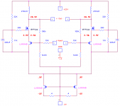
” . . . but . . .O.K. we can get a little closer to the ZV7-T. Nelson said he liked it
I wanted no capacitors their almost gone. I wanted Inductor loading like the ZV7-T
  I wanted JFETs Here is a Super Symetric version
But I still like the evolutionary variation of Grand Son Of Zen T
I wanted no capacitors
their almost gone. I wanted Inductor loading like the ZV7-T I wanted JFETs Here is a Super Symetric version But I still like the evolutionary variation of Grand Son Of Zen T
Attachments
Some further work in the design progress
Magura, I investigated your comment 2x80mH inductors
And, Carpenter I believe uses this value too The reason I used 270mH is basically to maintain gain to a minimum freq. I think the 270mH should not be down to 8 ohms until about 5Hz 2+ octives below 30Hz. O.K. I guess I'm over doing it However, I'm wodering about Nelsons comments regarding a Henry of inductance I guess the 80mH will be about 8 ohms at 15Hz. A full octive below 30
In my simulations I originally had trouble using a transformer model and reverted to 2 inductors until I straitened out some issues. However, I thought it time to re-think some of this bis.
The inductor load is not just an inductor. It is a coupled set of matched windings connected at the center tap. Or, a 1:1 transformer connected out of phase at one end. When doing this we cancel any feild with the Iq to be left with only the DC resistance as a load at idle, fine But, with differential action taking place caused by signal amplification, we dont see just the 80 or 270mH. We see the 2 in series making 4X the individual winding inductance. However, that would be only 2X per side. Isn't this thinking correct
Therefore, if we have 80mHs/winding, the actual load on each side will = 8 ohms at about 8Hz. Or bout 2 octives below your minimum expected frequency. Effectively a 160mH load???
Am I out in space or what
Thanks.
Magura, I investigated your comment 2x80mH inductors
And, Carpenter I believe uses this value too
The reason I used 270mH is basically to maintain gain to a minimum freq. I think the 270mH should not be down to 8 ohms until about 5Hz 2+ octives below 30Hz. O.K. I guess I'm over doing it However, I'm wodering about Nelsons comments regarding a Henry of inductance I guess the 80mH will be about 8 ohms at 15Hz. A full octive below 30 In my simulations I originally had trouble using a transformer model and reverted to 2 inductors until I straitened out some issues. However, I thought it time to re-think some of this bis.
The inductor load is not just an inductor. It is a coupled set of matched windings connected at the center tap. Or, a 1:1 transformer connected out of phase at one end. When doing this we cancel any feild with the Iq to be left with only the DC resistance as a load at idle, fine
But, with differential action taking place caused by signal amplification, we dont see just the 80 or 270mH. We see the 2 in series making 4X the individual winding inductance. However, that would be only 2X per side. Isn't this thinking correct Therefore, if we have 80mHs/winding, the actual load on each side will = 8 ohms at about 8Hz. Or bout 2 octives below your minimum expected frequency. Effectively a 160mH load???
Am I out in space or what
Thanks.
Hey Magura, the inductor wizard himself As ussual I've been sidelined a little with personal difficulties and such. I'm just now working again, and ready to invest in the DIYHobby further. I've since decided though, to try a different tacted. I really like the inductor loading idea but, I've decided to try a version of ZV9 with the Aleph Isource replaced with an inductor. This may explain where I'm at...
http://www.diyaudio.com/forums/showthread.php?s=&threadid=91922&highlight=
I am about to order the Hammond 195T5 chokes to use as the inductor load. The current idea looks like this...
As ussual I've been sidelined a little with personal difficulties and such. I'm just now working again, and ready to invest in the DIYHobby further. I've since decided though, to try a different tacted. I really like the inductor loading idea but, I've decided to try a version of ZV9 with the Aleph Isource replaced with an inductor. This may explain where I'm at...http://www.diyaudio.com/forums/showthread.php?s=&threadid=91922&highlight=
I am about to order the Hammond 195T5 chokes to use as the inductor load. The current idea looks like this...
Attachments
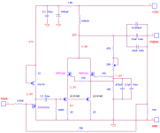
It's not that the Grand Son of Zen -T is forgotten, I would love to move on to that... I just wanted a traditional Single Ended design and my expectations for that classic sound are closer to being realized with the L Loaded ZV9...
I really had hoped Carpenter or someone would have tryed it because I knew I would not have had the time or $$$ until now. The circuit as it is seen here may need some refinements, as I was working with some inferior models for the JFET in Pspice back then. I do beleive I have a good inductor for a Balaanced/Diff type circuit now though. But, I really want to try the classic S.E. type ZV9 first
Give it a try
is forgotten, I would love to move on to that... I just wanted a traditional Single Ended design and my expectations for that classic sound are closer to being realized with the L Loaded ZV9...I really had hoped Carpenter or someone would have tryed it because I knew I would not have had the time or $$$ until now. The circuit as it is seen here may need some refinements, as I was working with some inferior models for the JFET in Pspice back then. I do beleive I have a good inductor for a Balaanced/Diff type circuit now though. But, I really want to try the classic S.E. type ZV9 first
Give it a try
Hmm, been there, done that....didn't like it better than the version I'm running now. It's more or less a ZV1 ccs instead of the aleph-ccs on a ZV9. Biggest difference from mine to your schematic is that I ended up with less global negative feebback.
If my memory serves me right, I used a 110k instead of your 75k.
This circuit is clearly not the way to get the full potential of the inductor load. It oviously has to be a differential pair and things running balanced. I've tried inductor loading both the standard ZV9 and the ZV1 as well. The ZV7TJ is clearly the best so far.
Magura
Magura, are your statements regarding the best use of inductor loading derived from the difficulty with DC in the inductor? I tried several large inductors and it was not just the inductance value, it was the saturation from the bias current that disturbs me. None of these however were meant to pass (no pun intended) any significant DC. They were all transformers. Both Toriods and EIs. The ZV7 type circuit should do fine with a resonable transformer. I'm thinking the 5 Amp DC rating of the 195T5 chokes will greatly aleviate that difficulty at least down to 60Hz or so. Hopefully lower. As you can see I'm hoping to get 3 Amps+ of Idle current and enough gain to drive the circuit without a pre. from my experimentation, the design I just posted, only has an open loop gain of about 16 or so and 1/2 of that will be used for F.B.(6db). I think the Aleph Isource versions benifit there...
Have you seen the Pathos Amps and the thread here?
http://www.diyaudio.com/forums/showthread.php?s=&threadid=10258&perpage=10&pagenumber=1
Or the...
http://www.diyaudio.com/forums/showthread.php?s=&threadid=24737&perpage=10&highlight=&pagenumber=1
I wonder what happened there???
BTW, just what do you mean by ZV1 ccs? Would that be more like a ZV8?
Yes I've seen those threads, but I havn't seen anything useful from either of them.
I have no DC issues as I run air core inductors exclusively (can't be bothered to trouble with all the issues other types of inductors bring to the table).
When saying ZV1 CCS, I meant the type of ccs used in the ZV1.
I for some reason I can't explain, don't like the sound of the Aleph CCS, at least not with any AC current gain of significance, and without the AC current gain, I think there is little point to the Aleph CCS.
Magura
Magura said:Hey...Carpenter...FLG....have you dropped off the face of the planet??
Magura
I hope not..........thinking about Carpenter's health issues.......
Zen Mod said:
I hope not..........thinking about Carpenter's health issues.......
I'm quite sure there's no need to worry, as they have both been online within the last day or so....
Magura


Somehow, I utterly missed this thread.
I just read the entire thing and like the company it houses. Hi guys.
Here's a tiny bit of thread jacking:
Health is improving enough to go back to work March 1st. --part time to begin with.
I've been experimenting with my own little (and I do mean little) version of a single-ended in to balanced out converter. It's a ZVP3310 diff pair with CCS and does a great job of boosting the gain in the ZV7-T. I've taken advantage of Express PCB's 3 pcbs for $51.00 offer. I even stuffed two circuits onto a card, so three is the magic number for 5.1 audio.
Hey Lee, you've got quite the imagination--you're pretty good with that simulator, too. I've been looking for a way to use my LU10XX jfets. Maybe I should try your latest layout. I must admit, though, the ZV7-T sounds pretty darn good as is. I've added four extra power FETs and an additional CCS in parallel with the current design. Nice. I also added 0.5 ohm resistors to the gain FET source pins to prevent current hogging. They're biased at 0.75 volts each, and now the transistors run much cooler.
FYI, I moved my preamp components to the front of the room so that they could be closer to the primary power amplifiers. Big difference in sound quality; everything's noticeably smoother.
Sorry for rambling on. Anyway, Lee, you're latest design is what I've been contemplating for some time. It's great to see your artwork; it gives me hope for my imagination. The more I think about it though, the more I just want to replace my ZV7-T's IRFP044 transistors with the Loveltech jobies. This is only to get 3 watts or so for my HF horns. I'd still use the buffers, they really make my current amps sparkle.
Bye for now,
John
I just read the entire thing and like the company it houses. Hi guys.
Here's a tiny bit of thread jacking:
Health is improving enough to go back to work March 1st. --part time to begin with.
I've been experimenting with my own little (and I do mean little) version of a single-ended in to balanced out converter. It's a ZVP3310 diff pair with CCS and does a great job of boosting the gain in the ZV7-T. I've taken advantage of Express PCB's 3 pcbs for $51.00 offer. I even stuffed two circuits onto a card, so three is the magic number for 5.1 audio.
Hey Lee, you've got quite the imagination--you're pretty good with that simulator, too. I've been looking for a way to use my LU10XX jfets. Maybe I should try your latest layout.
I must admit, though, the ZV7-T sounds pretty darn good as is. I've added four extra power FETs and an additional CCS in parallel with the current design. Nice. I also added 0.5 ohm resistors to the gain FET source pins to prevent current hogging. They're biased at 0.75 volts each, and now the transistors run much cooler.FYI, I moved my preamp components to the front of the room so that they could be closer to the primary power amplifiers. Big difference in sound quality; everything's noticeably smoother.
Sorry for rambling on. Anyway, Lee, you're latest design is what I've been contemplating for some time. It's great to see your artwork; it gives me hope for my imagination. The more I think about it though, the more I just want to replace my ZV7-T's IRFP044 transistors with the Loveltech jobies. This is only to get 3 watts or so for my HF horns. I'd still use the buffers, they really make my current amps sparkle.
Bye for now,
John
Hey John  Nice to here from you.
As you may have read, I'm collecting a few worthwhile components for the ZV9-L idea. I'm also getting around to putting my Circlotron amp in a chasis. I should be posting progress in a few weeks. A while back though, around the dawn of power JFETs, Grey posted a version of Circlotron using the JFET parts. You might be interested in that. I think he called it Nu-tron
So, as long as we are off thread here, when should we expect the latest release of a pass pre project??? I have to clean off the table for that one.
Nice to here from you. As you may have read, I'm collecting a few worthwhile components for the ZV9-L idea. I'm also getting around to putting my Circlotron amp in a chasis. I should be posting progress in a few weeks. A while back though, around the dawn of power JFETs, Grey posted a version of Circlotron using the JFET parts. You might be interested in that. I think he called it Nu-tron
So, as long as we are off thread here, when should we expect the latest release of a pass pre project??? I have to clean off the table for that one.
flg said:
So, as long as we are off thread here, when should we expect the latest release of a pass pre project??? I have to clean off the table for that one.
Hi, my friend. Afraid you lost me on this one. What Pass pre project?
John
Well, good to see that you're both still hanging in there
I made a test setup of a J-ZV7-T a while ago, which sounded better than all the other mutations I've tried so far (I've built most of the suggestions made on this board, counting out the buffer stuff). Now a clever guy would just post the schematic, but that's not going to happen cause I've lost it and the amp is no longer in one piece. It was obiously the way to go though!
I will try to find the time for making a new test setup (pretty hung up right now) and TRY not to loose the schematic before I get to post it
Magura
I made a test setup of a J-ZV7-T a while ago, which sounded better than all the other mutations I've tried so far (I've built most of the suggestions made on this board, counting out the buffer stuff). Now a clever guy would just post the schematic, but that's not going to happen cause I've lost it
and the amp is no longer in one piece. It was obiously the way to go though! I will try to find the time for making a new test setup (pretty hung up right now) and TRY not to loose the schematic before I get to post it
Magura
Hi Magura,
I assembled a jfet diff pair last night. I'm using the same schematic as for the ZV7-T mosfet version minus feedback loops. I bumped the gate to ground resistance to 220k and added 0.5 ohms to the source pins and 2 ohms between the drains and choke. I've worked her up to 12V, and have 0.5V on one source resistor, but no voltage reading on the other?
I have errands this morning, but want to continue with the experiment.
John
- Status
- This old topic is closed. If you want to reopen this topic, contact a moderator using the "Report Post" button.
- Home
- Amplifiers
- Pass Labs
- Gsoz-t